This section deals primarily with six remaining systems, five of which are unique to the LMFBR and the sixth, Liquid Radioactive Waste (LRW), is shared with LWRs. The five unique systems are the Auxiliary Liquid Metal (ALM), Sodium Water Reaction Products System (SWRPS), the Radioactive Argon Processing System (RAPS), the Cell Area Processing System (CAPS), and the Inert Gas Receiving and Processing (IGRP) system.
Auxiliary Liquid Metal
The Auxiliary Liquid Metal (ALM) system subsystems are 1) Sodium and NaK Receiving, 2) Primary Sodium Storage and Processing, 3) EVS Processing, 4) Primary Cold Trap NaK Cooling, and 5) Intermediate Sodium Processing. This subsection will focus on those subsystems which offer the greatest opportunity for cost reduction.
The Sodium and NaK Receiving subsystem was designed to receive sodium in 80,000 gal. railcars and NaK in steel drums. The system on CRBRP was designed for the capability to unload a railcar in 16 hours, a requirement that might be questioned. Otherwise, this system is straightforward and there isn’t much that can be said about it.
The Primary Sodium Storage and Processing subsystem is quite another matter. The system was designed to have the capability to totally drain the entire primary system into an in-containment storage tank, two tanks located in the Reactor Service Building (RSB), and the balance into the Overflow Vessel. The probability of being required to drain the entire primary system including the RV does not justify this requirement. The table below reproduced from the CRBRP PSAR is illuminating.
| | Ft1 | Gallons |
| Reactor Vessel drain | ||
| Reactor Vessel | 13,328 | 99,960 |
| PHTS piping which drains to the Reactor Vessel | 1,950 | 14,625 |
| Reduction in PHTS Na level | 2,328 | 17,460 |
| EVST reserve | 1,000 | 7,500 |
| Overflow/makeup piping | 625 | 4.688 |
| In-leakage from a single IHX leak | 1.350 | 10,125 |
| Total usable storage required | 20,581 | 154,358 |
Table 4 Total Primary Storage Requirements (Sodium Volumes at 400°F.
It is presumed that “Reduction in PHTS Na Level” means sodium in the PHTS loops that does not drain into the RV. “EVST Reserve” is also not clear (and not explained). The “In-leakage from a Single IHX Leak” probably is a calculation of the amount of IHTS sodium that would wind up in the primary system should there be an IHX tube failure. Elsewhere in the PSAR text it is stated that the in-containment primary sodium storage tank and the overflow vessel each have 35,000 gal capacities. Therefore, since the PSAR states that the total primary system storage capacity is 190,000 gallons, the two tanks located in the RSB must be sized at 60,000 gallons each. It is proposed that both of these tanks be deleted as CRM 45. The 35,000 gallon in-containment primary storage tank would have been sufficient to drain a single loop. Also, the 35,000 gallon Overflow Vessel (OV) was sized in part to meet the requirement for draining the total primary system and does not need to have a 35,000 gallons capacity to meet its requirements as an OV. The PSAR does state that the net sodium overflow volume of the PHTS from 400°F to THDV conditions is 1439 ft3, which is the principal requirement on the OV. Allowing for TOP transients at power, an OV size of about 2000 ft3 should be adequate and is captured as CRM 46. These numbers may need to be changed for the commercial-sized plant, but the underlying requirement would carry over.
The primary system cold traps provide yet another opportunity for significant cost reduction. Sodium proceeding to these traps is cooled first by a regenerative heat exchanger then a NaK cooler. The NaK in turn is cooled by a Dowtherm J system then chilled water. In contrast, the IHTS sodium cold traps are cooled also by a regenerative heat exchanger but in place of NaK, HVAC air is the ultimate heat sink. Use of the IHTS approach raises safety issues with the highly radioactive primary sodium should there be a sodium leak from the cold trap. However, the Dowtherm J has a temperature use range from -100°F to 575°F so it could be used in place of the NaK. This measure is captured as CRM 47.
There is a drain vessel associated with the primary sodium makeup pumps. There is no obvious need for a drain vessel for these pumps that is separate from the in-containment primary system storage tank and it should be considered for elimination as CRM 48. Elimination of components in this system eliminates ALM piping connections, inert gas services, associated instrumentation and operational monitoring, simplifying plant operation.
The EVS Processing system consists of two loops with EVST sodium leading to a sodium to NaK heat exchanger then to an EM pump and back to the EVST. On the NaK side, coolant flows to an air blast heat exchanger, an EM pump, and back to the sodium to NaK heat exchanger. In addition, there is a third loop with naturally circulating sodium from the EVST leading to a sodium to NaK heat exchanger. The NaK side also naturally circulates to a natural draft heat exchanger. The third system was made necessary to meet the single failure criterion with one loop out of service.
The CRBRP system may well be the optimum system for this service. A change that might be considered would be to borrow the idea that led to the Overflow Heat Removal System; namely, make the two normal heat removal systems naturally circulating and have the third loop circulated by an EM pump to a sodium to NaK heat exchanger that ties into the PRACS on its NaK side.
The Intermediate Sodium Processing subsystem may also be close to the optimum system. However, since the design concept has just two intermediate loops, there would be just two Intermediate Sodium Processing subsystems as opposed to three in CRBRP.
SWRPS
Beginning with the SWRPS, since a drawing of the system is not included in the CRBRP PSAR for some reason; the figure below captures the essential features of a typical system. If there were to occur a significant sodium water reaction such as caused by a tube rupture inside the steam generator, large quantities of hydrogen would be produced (2Na + 2H20 → 2NaOH + H2) causing a pressure pulse on the sodium side, causing a surge of sodium into the expansion tank, failing rupture disks to the separation tanks, and shutting fast acting feedwater and IHTS sodium valves. The inlet to the separation tanks enters the tanks tangentially causing a swirling action that separates the reaction product (NaOH) from un-reacted sodium and hydrogen. The un-reacted sodium drains into the sodium dump tank while the hydrogen is directed up a flare stack, failing a rupture disk there. If the argon float on the expansion tank cannot keep up with the increasing pressure there, a rupture disk could also fail on the argon side of the expansion tank, venting argon to the dump tank.
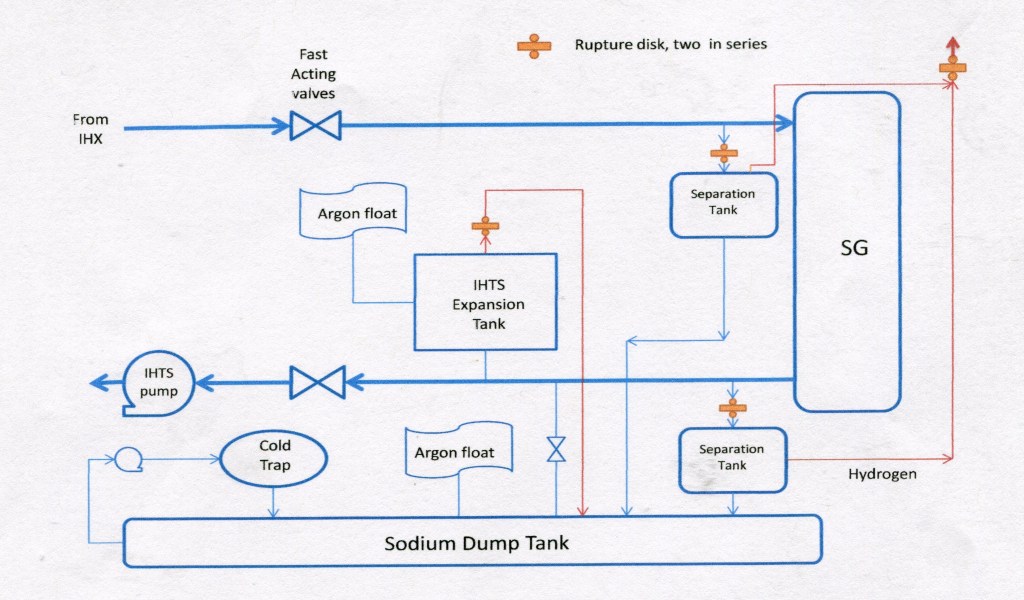
Figure 39 Typical Sodium Water Reaction Products System
Hydrogen passing up the flare stack fails rupture disks located there. In the interest of preventing an explosive mixture of hydrogen and oxygen in the atmosphere above the flare stack, the hydrogen is ignited as it passes a non-return valve at the stack exit. The stack itself is normally purged with nitrogen between the rupture disks and the non-return valve to prevent an explosive situation from occurring in the stack should there be a SWRPS actuation. Nitrogen is also supplied to the sodium system to dilute the hydrogen and replace the sodium that is rapidly being drained.
In the design of this system, the lines to the separation tanks and the expansion tank should be as close to the steam generator as possible in the interest of providing relief to the steam generator and minimizing contamination of the IHTS. Some systems may provide a cover gas in the sodium side of the steam generator expressly for the purpose of absorbing some of the pressure pulse attendant to a sodium water reaction. Following any significant sodium water reaction, the effected steam generator may require replacement and the separation tanks will be cut out and replaced. Reaction products in the dump tank will be removed by the associated cold trap and any remaining IHTS sodium will likely be drained into the dump tank for processing by the cold trap.
This is probably a system that is ripe with opportunities for improvement, but none are obvious, so the following discussion will be directed to areas where opportunities are more transparent.
The Inert Gas Receiving and Processing (IGRP) system on the CRBRP was comprised of four subsystems, the Argon Distribution System, the Nitrogen Distribution System, the Radioactive Argon Processing System (RAPS), and the Cell Area Processing System (CAPS). The better understanding of the system will be achieved by beginning with RAPS, proceeding to CAPS, then the IGRP and Nitrogen Distribution systems.
RAPS
The figure below shows a process flow diagram for RAPS as it was designed for CRBRP.

Figure 40 CRBRP Radioactive Argon Processing System (RAPS)
The numbers shown in the figure are the flow rates in SCF/min. In the center of the diagram, a pressure equalizing line for the reactor vessel, overflow vessel, and PHTS pumps is evident. RAPS is intended to serve those components plus the fuel failure monitoring system. The vessels and pumps exhaust through vapor traps to a vacuum vessel, then to a compressor and surge vessel on their way to a cryogenic still that separates the xenon and krypton from the argon before proceeding to the recycle argon storage vessel. The sodium vapor traps are provided to condense any sodium iodide that might be entrained in the cover gas preventing it from flowing into the processing system.
The fuel failure monitoring system is an obvious candidate for elimination. It was planned for installation on CRBRP partly because of the government’s involvement and an associated intent to derive experimental data from that project. Nonetheless, the CRBRP PSAR acknowledged “the failed fuel monitoring system is not required to operate when there are more than 60 failed fuel pins”, which corresponds to 0.17% failed fuel. The plant was designed for operation with 1% failed fuel. This amounts basically to an acknowledgment that the system is not required. The elimination of this system was previously identified as CRM 5, which eliminated gas tagging of fuel assemblies.
Since the proposed design concept replaces the centrifugal PHTS pumps with EM pumps which do not require cover gas, that part of the RAPS system can be dispensed with. It is worthy of pointing out that the RAPS included an oil vapor trap downstream of the PHTS pumps. The PHTS pump seals were gas seals that were lubricated with oil. Although most of the oil passing the seals would be carried away by the RAPS, inevitably some of the seal oil would find its way into the PHTS sodium, where, after reacting with the sodium, it would need to be removed by the cold traps, shortening their life. Thus, another advantage of EM pumps manifests itself. The pump seal purge was the single supply to RAPS than could not be halted. With the pump seal purge out of the picture, the opportunity of halting RAPS processing flow becomes an option – one that will be exercised later in this discussion.
A third simplification would be to eliminate the recirculation line. The CRBRP PSAR states “The recirculation-loop feature in RAPS permits maintaining a steady throughput under conditions of changing output demand requirements.” This recirculation line is a relatively small matter, but it was made necessary on CRBRP since the compressor was operated at constant flow rate of 10 CFM. The compressor for the current design will be variable speed, eliminating the need for recirculation. Once the pump seal purge and failed fuel detection purge have been eliminated, the only real reason for having RAPS is to remove Kr85. Among the fission product inert gasses, Kr85 is the only one with a relatively long half life of 10.76 years. The next longest lived inert gas fission products are Xe131m with a half life of 11.96 days and Xe133 with a half life of 5.27 days. Of these two, Xe133 is the more challenging because of its greater fission yield.
In the CRBRP design, the cryostill was intended to be operated at liquid argon temperature of -302.5°F. This compares with liquidus temperatures for krypton and xenon of -244.1°F and -162.6°F respectively. The designer’s intention was that krypton and xenon (mainly krypton) would collect in the cryostill and once a year they would be bled off into the noble gas storage vessel. After a few weeks, the only gas left in the storage vessel would be Kr85, which would subsequently be discharged to atmosphere in a controlled fashion. Since there would be only about 700 Ci of Kr85 produced in a year, such a procedure would be acceptable.
The xenon isotopes do complicate the design of RAPS, however, since so much xenon is produced in fission. The table below reproduces data from the CRBRP PSAR (except for the last column) defining the production rate of the inert gas isotopes assuming operation with 1% failed fuel. The fifth column shows the radioactive load in Curies on the cryostill after a year of operation. With the exception of Kr85, these are all equilibrium loads which are reached after a month of operation – only the Kr85 continues to build. The inventory in the cryostill gives a fair approximation of what the inventory of radioactive fission gases in the cover gas would have been had there been no RAPS. This observation will become important in the discussion that follows. The final column shows the energy load associated with the named isotope on the cryostill.
| Isotope | Half life | Decay constant (per day) | Input rate (Ci/day) | RAPS cryostill load (Ci) | Energy load (watts) |
| Xe131m | 11.96 day | 0.058 | 112 | 1900 | 0.5 |
| Xe133m | 2.23 day | 0.306 | 3760 | 1.1E4 | 2.9 |
| Xe133 | 5.27 day | 0.131 | 65,100 | 4.7E5 | 319 |
| Xe135m | 15.7 min. | 63.6 | 95,600 | 2.0 | 0 |
| Xe135 | 9.16 hr. | 1.81 | 334,000 | 8.8E4 | 165 |
| Xe138 | 14.2 min. | 70.2 | 170,000 | 2.5 | 0 |
| Kr83m | 1 86 hr. | 8.98 | 16,400 | 160 | 0.4 |
Table 5 CRBRP Radioactive Nuclide Input Rates to Reactor Cover Gas & Radioisotope Load in Cryostill
The total energy load on the cryostill turns out to be 502 watts, of which 14.5 is attributable to krypton isotopes (mainly Kr88) and the balance, 487.5 watts to xenon isotopes. This 502 watt load on the CRBRP cryostill would need to be taken into account in the engineering design of RAPS, but was not considered important enough to deserve mention in the PSAR.
With the design contemplated, the picture changes. The plant’s thermal power is three times that of CRBRP and it is proposed to use vented fuel. Thus the radionuclide input rates and associated energy loads theoretically increase by a factor of 300. Discharging 210,000 Ci/yr. of Kr85 to the atmosphere annually would probably not be well received, and assuming RAPS flow rates increase by a factor of 3 to account for the higher thermal power, the thermal load on the cryostill could be the 150 KW range. Loss of power to such a system or any of the other RAPS components has the potential of producing a large source term that would challenge containment.
First, consider the Kr85 problem. 210,000 Ci seems a formidable number, yet its volume turns out to be just 140 liters or about 5 ft3 at STP. It would generate about 230 watts of thermal energy. While there are stable isotopes of krypton that are fission products and will be present in the cover gas along with Kr85, even if the total krypton volume is an order of magnitude greater, these are numbers that would suggest that long term storage would be manageable over the expected lifetime of the plant.
Second, consider changes that could be made to the RAPS flow rate. On CRBRP, the RAPS flow rate was 5.15 ft.3/min., which included the flows from the overflow vessel, the pumps, and the fuel failure monitoring system. The design basis of the CRBRP RAPS is to “maintain the cover gas at an acceptable level of radioactivity” (“acceptable” not defined), to provide a source of low radioactivity gas for the head seals, and for cover gas pressure control. The head seal leakage is identified in the RAPS section of the PSAR as being 7 SCC/min., which works out to be 0.00025 ft3/min. Therefore, of these three criteria the most likely to govern RAPS flow rate is the cover gas pressure control. When the plant starts up from shutdown, the RV sodium expansion causes the RV to overflow to the Overflow Vessel thus reducing the total volume of the cover gas between the RV, Overflow Vessel, and PHTS pumps, which winds up in the RAPS storage vessels. Since the storage vessels are maintained at a higher pressure than the cover gas, the only way to get it there is through the RAPS. The calculated rate of expansion for the conceptual design selected for this study turns out to be approximately 3 ft3 per minute for a power level change of 1% per minute, which is reasonably consistent with the 5.15 ft.3/min. given the higher sodium inventory of CRBRP.
There is no reason why cover gas pressure control needs to be accomplished using the same system that is used for cover gas processing. A separate compressor could tap into the equalization line through a sodium vapor trap, discharging to a surge vessel, a flow control valve, then back to the equalization line. A flow rate of 3.0 ft.3/min. for this system should be adequate. Once having provided this separate system for cover gas pressure control, the RAPS processing flow rate can be reduced by at least a factor of 100. Reducing the RAPS flow rate reduces the energy burden on the processing system components and allows some decay to occur (particularly Xe135 and Kr88), although this benefit is reduced because of the 5.27 day half life of Xe133. The figure below shows a revised potential system, where the flow numbers are on ft.3/min.

Figure 41 Proposed Cover Gas Control & Processing System
It is necessary to give consideration to the factor of 300 for the energy difference of the cover gas activity between CRBRP and the design concept. In the CRBRP, it was assumed that all the fission gas associated with 1% failed fuel immediately found its way into the cover gas. Since a fuel element failure could occur in the region of highest heat production in the fuel element, such an assumption is semi-plausible and it certainly is conservative. If the plant systems can handle the consequences associated with such conservatism, making the assumption avoids justifying a lower number. Since the assumption is troublesome given the design approach being contemplated, it needs to be reconsidered.
The fission gases are born in the fuel pellets and it is necessary for them to migrate to the plenum above the fueled area in order to make their way to the reactor coolant and then to the cover gas. The amount of time that is required for such migration to occur under the circumstances envisioned in the design approach being advocated is unknown, but it cannot be instantaneous. After a relatively short period of plant operation, the pellets are in intimate contact with the clad, so gas must migrate upwards through the pellet column including passing through the upper axial blanket. If this process requires as much as two weeks on average, the cryostill problem is solved – most of the xenon will have decayed in the fuel.
The technical literature is rich in articles on fission gas migration in oxide fuels. It appears to be widely accepted that there is little migration of fission gas in fresh fuel up to a burnup of about 5%, when the fission gas bubbles begin to agglomerate and migrate along grain boundaries. Other areas of common ground in the technical literature are that migration occurs at a higher rate as temperature increases, and migration can be accelerated by transients. At higher burnup, the gas migrates along grain boundaries, but these boundaries won’t be lined up when the gas moves up from one pellet to the one above it, which further retards the process. The effect of the upper axial blanket on retarding flow is something that does not appear to have been addressed, but it should present another rather formidable barrier. Many of the upper axial blanket pellets will have swollen making intimate contact with the clad, but will not have agglomerated fission gas bubbles expanding grain boundaries in the same fashion as the fueled regions. A fair amount of pressure buildup will be needed to pass this barrier. Once the fission gases finally pass the upper axial blanket and arrive in the coolant, some will dissolve or be entrained in the coolant stream and remain there until they finally make it to the cover gas. The time required for this to happen is something that should be amenable to experimental determination.
Part of the answer to all this complexity and uncertainty is to make the RAPS processing rate variable in the range from 0.01 to 1 ft.3/min. The flow rate would be determined by the activity of the cover gas – when it exceeds 1 watt/ft.3, its flow would be reduced in accordance with a predetermined formula down to as low as 0.01 ft.3/min. There is no need to consider rates as high as to those planned for CRBRP, since at 1 ft.3/min., the cover gas will be turned over once daily and the DF of the processing system is so high that 5-7 turnovers will suffice for most purposes. Refueling occurs so infrequently, it can await satisfactory cover gas activity levels. There may be some cases where the processing system would be shut down completely to await xenon decay, i.e. following a transient. In any case, flexibility is necessary for a satisfactory RAPS design.
As was stated earlier the Overflow Vessel on CRBRP has a capacity of 35,000 gallons or about 4700 ft3. The PSAR states in a table that the net sodium overflow volume from 400°F. to THDV conditions is 1439 ft3. The total primary system volume at THDV was 23802 ft3. Presumably, there is some allowance in the Overflow Vessel for overpower transients – perhaps 300 ft.3.
The CRBRP RV cover gas volume was 410 ft.3, which compares with the design concept cover gas volume of about 750 ft.3. The Overflow Vessel needs to make an allowance for overpower transients occurring at full power, so another 250 ft.3 should be adequate for that purpose. Between the reactor and the overflow vessels, the total amount of cover gas is 1000 ft3. At a rate of 0.01 ft.3/min., the entire cover gas volume would be processed in about 70 days. The dominant reason for RAPS processing is to provide a means for removal of Kr85, which is insensitive to processing flow rate. Slowing the processing allows more xenon to decay in the reactor vessel where it contributes a little to plant power level. In fact, it could be argued that the approach of having a separate system for cover gas pressure control could have been taken on CRBRP so as to reduce the burden on the processing system.
It is necessary to consider the effect of the higher cover gas energy level on the RAPS processing components. Assuming that the reactor cover gas has a volume of about 750 ft.3 at full power, the cover gas could have an energy level as high as 200 watts/ft3 if CRBRP PSAR assumptions are used. The cover gas control surge vessel would not experience such a high level since it would mainly be filled during plant startup when the plant would be operating at low power after it had been shutdown. Assuming power level at startup to be 5%, cover gas energy level would be at most 10 watts/ft3 (more likely, close to zero). If the surge vessel were sized for 1500 SCF, it would have a heat load of at most 15 KW, dropping to under 10 KW once the Xe135 has decayed. This should be a fairly manageable engineering problem.
Another occasion when the cover gas control surge tank would be filled would be during the up transient associated with load-following. From 15% to 100% power there would be 3 SCF per minute flowing into the surge tank for 85 minutes for a total of 255 SCF. So long as the cover gas energy is less than 50 watts/ft.3, the surge tank would be okay, but would not be able to handle a similar load-following transient the following day. A decision on load following capability would need to be made based on the activity in the cover gas.
In order to design the RAPS processing system components, it is necessary to decide the level of cover gas energy they will be obliged to process – the idea being that on the rare occasions of higher energy levels in the cover gas, the RAPS processing system will be shut down until the levels decline. The key parameter is the time required for the fission gases to escape from the fuel pin, enter the coolant, and then enter the cover gas space. This is something that can be supported by experimental data when the time comes to embark on preliminary design but for the purposes the current work, one week will be assumed to be reasonably conservative. After a week, the fission gas isotopes have decayed such that their contribution to the cover gas energy is down by 76%. This corresponds to about 50 watts/ft3 in the cover gas.
If the components in the RAPS processing system are obliged to handle cover gas at energy levels of 50 watts/ft3, they must be resized from their CRBRP version. There appears to have been about 1400 ft.3 of cover gas in the CRBRP design (400 in the RV, 400 on the Overflow Vessel, and 200 in each of the PHTS pumps). From the PSAR data, the RAPS surge vessel contained about 3600 SCF, the vacuum vessel between 125 and 206 SCF (pressure varying between -7 and -2 psig), the Recycle Argon Storage Vessel 2200 SCF, and the cryostill 58 SCF. There is no need for such a large surge tank when the compressor speed is variable, especially since RAPS system surge can be accommodated in the Recycle Argon Storage Vessel, which stores gas after it has been processed. The only purpose for the Surge Vessel would be to absorb any pressure pulses from the compressor. If the vacuum vessel and surge tank were reduced in size to about 40 SCF, the attendant heat loads would be a manageable 2 KW. Since isotopes are being concentrated in the cryostill, its size is not as important. An approach might be to put some sort of delay device in the circuit ahead of the cryostill to allow isotope decay. Because of the 5.27 day half life of Xe133, this approach would only marginally improve things unless the delay device was sized to be about 100 ft3. At 0.01 ft.3/min. processing rate, a 100 ft3 delay device would reduce the Xe133 concentration another 63%. Such a device might consist of a 2 ½ in. diameter coiled tube with a total tube length of 3000 ft. It is shown as optional with a bypass, which would be mandatory at higher flow rates, in Figure 37.
It remains necessary to consider the overflow vessel. On CRBRP, the RAPS took suction on the overflow vessel, so the cover gas in the overflow vessel was the same as the reactor. At full power, the overflow vessel would be nearly full of sodium, but there will need to be some cover gas left to accommodate overpower transients – say 250 ft.3. There is no reason to burden the overflow tank with high energy cover gas if it can be avoided. Since there is little if any flow in the equalization line during steady state conditions, a simple solution would be to take the RAPS processing line off the equalization line as close to the reactor as possible. Another fix would be to design the overflow connection to the reactor so as to avoid entrained cover gas in the reactor overflow. This could be accomplished by simply providing a small downward pointing pipe connecting to the overflow penetration interior to the reactor vessel. Heat generated in the overflow tank would eventually be returned to the reactor via the overflow pumps, but it would be desirable not to be obliged to rely upon this mechanism. In the event that the Overflow Vessel cover gas becomes contaminated to levels approaching unacceptability, Figure 37 shows the capability to switch RAPS processing from the reactor to the overflow tank.
The discussion in this subsection has assumed the cover gas is argon while earlier helium was given as the preferred cover gas for the design concept. The design of the cryostill would certainly be different with helium cover gas and it is unlikely that one would use liquid helium as the carrier medium. Both krypton and xenon are solids at liquid argon temperatures, so one could use liquid argon or nitrogen to condense (and freeze) the krypton and xenon, with a barrier separating the argon/nitrogen from the helium cover gas and the chunks of frozen xenon and krypton. The design of a cryostill for this application shouldn’t pose much of a problem. The remainder of the components would work for either cover gas.
CAPS
A flow diagram of the Cell Area Processing System or CAPS as it was designed for CRBRP is shown below. The figure is a reproduction of a similar figure appearing in the PSAR except in the PSAR, the HEPA filter was omitted. The solid boxes are CAPS components.
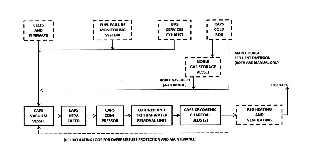
Figure 42 CRBRP Cell Area Processing System (CAPS)
Regarding the CAPS inputs, the Gas Services Exhausts are intermittent and are located at various stations around the plant – CAPS would receive exhausted nitrogen, argon, or air from vessel cover gases, cooling gases, cleaning, bagging, and fuel handling operations, and other services. On CRBRP, it was the intent to purge the cryostill annually, with the argon from the still directed to CAPS and the noble gases to gas storage, where it would be bled to CAPS over a fixed period of time. The fuel failure monitoring system continuously discharged about 1 ft3/min to CAPS, as shown on Figure 38. The only input to CAPS that was continuous was the cells and pipe ways where a purge stream of about 38 SCF/min was maintained. The idea was that cover gas leaking through various seals and tritium leaking through pipe walls would be captured in CAPS and treated prior to release to the atmosphere.
A recirculation loop, shown by a broken line in Figure 38, returns the CAPS output to the vacuum vessel if radioactivity above an acceptable level is detected by the radiation monitoring system. Also, if the effluent radioactivity is high, the CAPS compressors will be shut down. The tritium-water and alcohol removal process uses an oxidizer and a freeze-out, dryer; it oxidizes tritium, collects tritiated water and alcohol and passes them to the Radioactive Liquid Waste System, where they are prepared for off-site disposal. The decontamination of radwaste gas is performed in two cryogenically-cooled charcoal delay beds. In the beds, the short-lived gaseous radioactive species are adsorbed and then decay; they are thus removed from the process gas stream. RAPS and CAPS have different process methods, i.e., the distillation-process removal of noble gases in RAPS rather than the delay beds and the oxidation process removal of tritium in CAPS. In each subsystem, however, the input is collected in a vacuum vessel, from which it is transferred to a surge vessel. It is then treated in the respective cold box.
The oxidizer for tritium is obvious overkill. In an LMFBR, there is no tritium production from neutron absorption by deuterons and the only source of tritium is from fission, where the expected production rate is less than 1 per 104 fissions. The PSAR states that at least 99.8% of the tritium will combine with sodium and be removed by the cold traps. The main source of tritium is expected to be that which diffuses trough the PHTS and IHTS pipe walls. The total annual release rare for tritium is given as 0.069 Ci/yr and the DF of the tritium removal unit is given as 100. Thus, if there had been no tritium removal unit, the tritium release would be 6.9 Ci/yr, (given the conservative assumptions used) which compares with the releases from other sources of 1700 Ci/yr, 1200 of which is Kr85. The elimination of the tritium removal unit is CRM 49.
Although it is not explicitly stated in the CRBRP PSAR, CAPS is a backup for RAPS. The CAPS cryogenic charcoal beds therefore play an important role when they are viewed from this perspective. The charcoal beds delay the xenon isotopes until they decay before release. This is probably the most important function performed by CAPS. The CAPS for the design concept would be much the same as its CRBRP counterpart with the fuel failure monitoring system and the tritium removal unit deleted and the HEPA filters placed at the end, rather than the beginning, of the process.
IGRP System
Although technically, RAPS and CAPS are part of the IGRP system, for the purposes of the discussion, the IGRP system minus RAPS and CAPS will be treated separately. IGRP minus RAPS and CAPS is basically a system for the distribution of argon and nitrogen throughout the plant. This turns out to be important for the main purpose of proposing a design approach that meets the basic requirements without unnecessary provisions that add cost and complexity to the plant without commensurate benefit. One of the first things that greets the reader of the IGRP sections of the CRBRP PSAR is that there are 12 P&ID drawings for the argon distribution system and 12 P&ID drawings for the nitrogen distribution system. This system turns out to sprawled out all over the plant with miles of piping and hundreds of valves. It is ripe with opportunity for cost saving.
Of the 12 P&IDs for the argon distribution system, 5 are for the RSB, 5 are for the RCB and 2 are for the SGB. Starting with the SGB, close examination of the P&IDs reveals that there is much that is unnecessary. It appears that the designer’s approach was to provide permanent systems for applications which may only occur seldom in the life of the plant. For example, there is argon piping to four locations for intermediate sodium cold trap line venting. The piping leads to a shut off valve and a spool piece. The idea being that when one needs this feature, the spool piece is installed. The only time this would ever be used is when the intermediate system cold trap is being replaced, which occurs perhaps once every 20 years. In addition to the pump cover gas, there is a pump seal purge to the lower seal and its associated oil collection tank and oil trap; there is a pressure equalization line between the pump and the IHTS expansion tank; and there is a supply line to the pump seal oil supply tank. Here are three more good reasons for using an EM pumps for the IHTS. The SGB has its own bank of liquid nitrogen storage vessels, associated vaporizers, filters and numerous associated valves. It also has an auxiliary argon supply. Once the pumps and once in a blue moon connections are deleted, the only things needing argon in the SGB are the Sodium Dump Tank, the IHTS Expansion Tank, and the spaces between the rupture discs in the SWRPS system. There is no reason why any needed argon for these services can’t be supplied from the RSB.
In the RCB there are 17 spool piece connections, all of which could be eliminated. When there occurs a rare need for argon to be supplied to one of these points, it could be accomplished with hose. There is no need for permanent installations and spool pieces that are likely to disappear long before they are needed. As was the case with the SGB, replacing the PHTS centrifugal pumps with EM pumps eliminates nine connections. The pressure equalization lines connecting the OV to the PHTS pumps are in this system. A careful review of the five P&IDs for the RCB would undoubtedly lead to many other options for cost reduction. Systems such as this receive relatively little oversight from the customer organization and as a result, they grow in such a fashion so as to satisfy every possible perceived need. If the system designer receives little in the way of feedback there is a tendency to add to the system, usually unnecessarily. This system is a good example of the devil in the details and a good opportunity for cost reduction. It is captured here as CRM 50.
Dowtherm J
Dowtherm J is an organic heat transfer fluid that does not react either with water or the alkali metals that was used in two places on the CRBRP plant, 1) as the cooling fluid for the NaK that was used for the primary system cold trap. It in turn was cooled by chilled water. 2) the space coolers in the fuel handling cell were cooled by Dowtherm J, which were in turn cooled by chilled water.
Dowtherm J would be needed as the cooling fluid for the space coolers of the refueling cell in the concept being advanced. It should be noted that Dowtherm J was planned for use on the CRBRP plant nearly 50 years ago. It was an improvement over the cooling fluid used by FFTF for similar applications called Mobiltherm. In the intervening years, it is likely a more advanced fluid exists that could replace the Dowtherm J, although Dowtherm J continues to be marketed by Dow.
Once a suitable cooling fluid has been identified, a careful assessment of the possibility of using that fluid in place of NaK, everywhere NaK is used should be performed. NaK is more reactive than sodium and since it is liquid at room temperatures, a leak of NaK is considerably more difficult to contain and control than a leak of sodium, which usually freezes at the leak site. Eliminating NaK everywhere it exists in the plant would be a big positive for the LMFBR. This item is captured as CRM 51.
An important qualification to this cost reduction measure is the experience of the SRE with Tetralin, which was used to cool the seals on the primary sodium pumps. The Tetralin made its was into the primary system and caused plugging of several fuel assemblies leading to their overheating and meltdown. Armed with that experience, Tetralin was replaced with NaK everywhere it existed in the primary system and was not used on Hallam. 73 A NaK leak into the primary system is not without consequences, but NaK will not interfere with core cooling.
Nitrogen
In the CRBRP design, nitrogen supplied 1) a low pressure header feeding all of the normally inerted cells and pipe-ways within containment and the RSB, 2) a high pressure line for actuation of valves in cells that are normally inerted, 3) a line to the CRDM assembly recirculation cooling system, 4) a line to provide sparging gas to the sodium component cleaning operation in the RSB, and 5) a line to purge the RAPS cold box, 6) the CAPS cold box is inerted with nitrogen at a continuous low flow rate during operation in order to provide a dry, non-frosting, non-condensing atmosphere, 7) for service maintenance operations available at service stations located within the RSB, 8) a controlled pressure N2 supply is provided separately to the autoclave located in the RSB, 9) as a cover gas for the Dowtherm tanks used in the chilled water system, and 10) as a cover gas for the SWRPS in the SGB.
There are obvious places where economies can be made in this system. As was the case with argon, the both the RSB and the SGB had their own supply of nitrogen in the CRBRP design, which was unnecessary. For nitrogen, there is a greater need for a large supply to be available in short notice to support the SWRPS than anywhere else in the plant. If SWRPS is activated, nitrogen must fill the volume previously occupied by sodium in the effected steam generator and to purge the hydrogen generated by the sodium water reaction. Therefore, it might make sense to eliminate the separate RSB supply and have the entire plant supply originating in the SGB. Also as was the case with argon, there are numerous connections requiring spool pieces, most of which can be done away with.
Liquid Radwaste
There are two sources of liquid radwaste in the CRBRP design; the sodium removal and decontamination system and plant drains. Plant drains include the personnel shower, and all the cell drains throughout the plant. Each of these two sources has its own subsystem consisting of a filter, collection tanks, another filter, an evaporator, a demineralizer storage or monitoring tanks, and either discharge or reuse paths. Six complicated P&IDs are required to describe this system. All this complexity is provided so as to reduce the dose to the most exposed member of the public who obtains all his or her drinking water from the nearest point adjacent to the plant offsite to 0.13 mrem/year. This is a sad tale of woe common to every nuclear plant in the country.
There is nothing that can be done about floor drains or showers, but the system intended to prepare sodium wetted spent fuel for shipment, which is by far the largest radioactive source for the liquid radwaste system, does not need to be available until 15 years after startup of the plant, at the earliest. If it were possible to ship sodium wetted spent fuel to the reprocessing facility, a large cost driver could be eliminated. Since the systems for treating floor drains and showers is separate from the system for cleaning sodium wetted fuel, the latter system can be added to the plant 15 years downstream. Section 14 describes the fuel cycle facilities necessary to implement a power supply system that includes LMFBRs and describes the need for committed reprocessing facilities for LMFBRs. If the first such facility were co-located with the LMFBR, the need for a radwaste system for treating effluent from a sodium cleaning facility would be obviated. Deferral or elimination of this system is captured as CRM 52. Space should be provided in the RSB for its eventual installation.
Endnotes
1 R.J. Beeley, J.E. Malmeister, Operating Experience on the SRE and its Application to the Hallam Nuclear Power Facility, Atomics International, 1961.
