In the final analysis, the CRBRP Primary Heat Transport System (PHTS) was quite elegant, combining some of the best ideas from its American and German predecessors. Figure 22 is a schematic of one loop (of three).

Figure 22 CRBRP HTS Schematic
The PHTS pumps were located in the hot leg as was done in FFTF and the German SNR-300. This was done so as to enable maintaining atmospheric pressure in the reactor vessel at all times. If the pump had been placed in the cold leg, it would have been necessary to pressurize the reactor above atmospheric to ensure the pumps would have adequate suction head during full flow operation because of the pressure drop across the IHX.
The Steam Generating System (SGS) consisted of two evaporators and one superheater per loop. The steam drum had a two for one recirculation ratio. Decay heat was removed from the steam drum via an air blast heat exchanger. There was an auxiliary feed water supply to the steam drums supplied with 1E power when the normal feedwater pumps were not available. One of the auxiliary feedwater pumps was driven by steam from the steam drums.

Figure 23 CRBRP HTS Containment Layout
The entire PHTS piping circuit including all expansion loops was maintained at a constant elevation. The expansion loop between the primary pumps and the IHXs protruded outward and established the containment diameter as is evident in the figure above, which is one of the primary defects of this design. The containment diameter of 186 ft. is considerably greater than commercially sized PWRs and resulted in much wasted space in an area that has very high real estate value.
A discussion of the PHTS would not be complete without a treatment of the overflow system, shown below as Figure 24. The RV continuously overflows to the Overflow Vessel while EM pumps take suction on the vessel and return sodium to the RV. The overflow vessel performs many of the same functions as the pressurizer in PWRs, maintaining inventory control through variations of the primary system temperature or power level changes. At operating temperature, the overflow vessel is nearly full, while it is at minimum level during refueling operations. Included in the overflow circuit are the cold traps, which remove oxygen and other impurities from the sodium. Figure 24 also shows the Overflow Heat Removal System (referred to on the CRBRP project as the “direct heat removal service”) and the cooling system for the EVST.
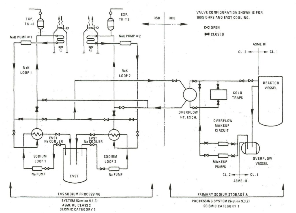
Figure 24 Overflow System, Overflow and EVST Heat Removal Systems
Since one of the very few places in the world that has performed any relatively recent work on loop-type designs is Japan, it would be well, when embarking on a treatment of the heat transport system (HTS) to start with an examination of the 1500 MWe Japan Sodium Fast Reactor (JSFR-1500). There have actually been two loop-type conceptual designs developed in Japan since Monju, the demonstration fast breeder reactor (DFBR) and more recently the JSFR-1500. The DFBR is a 660 MWe design embodying the so-called top-entry loop which was retained by the JSFR-1500. In fact, many of the JSFR features are a scale-up of the DFBR, so for the purposes of this discussion the following will be based on the more recent JSFR-1500. Most of the Japanese effort on this design that has been made available in the open literature seems to be focused on their safety approach and core design and there is woefully little on the heat transport system, but if one starts with what is available and uses a little imagination, it is possible to put some of the pieces together. A conceptual rendering of the JSFR-1500 HTS is shown below in figure 25. By way of comment, representatives from Japan who describe their activities claim that in Japan future work will be based on the loop “to take advantage of Monju experience”. While that may be true, the Japanese vendors are fully capable of designing a pool-type reactor and have possibly chosen the loop because they have concluded it has more economic potential. There was considerable design activity at all four of Japan’s reactor vendor design groups (Toshiba, Hitachi, Mitsubishi, and Kawasaki) funded by CRIEPI that was focused on the pool design in the 1980s.

Figure 25 JSFR-1500 heat transport system
The JSFR-1500 has two primary loops and two secondary loops. The primary pumps appear to be centrifugal and have been integrated with the IHXs so as to eliminate the pump vessels, their associated guard vessels, and the interconnecting piping. The IHX tube bundle has been elevated above the reactor core to promote PHTS natural circulation. The designers refer to their concept as “through the head”, which presumably means the reactor inlet and outlet piping penetrates the head rather than being routed through nozzles on the reactor vessel wall. There is precious little on the subject of refueling, but it was reported31 that there is one pantograph machine and one rotating plug. A “pantograph” is an in-vessel handling machine with a scissors-like arrangement allowing variable extension in-vessel in the horizontal direction. Figure 26 below shows a “Plug Rotation Mechanism” and a single rotating plug but no indication of the location of the pantograph. Presumably, the single rotating plug is offset to allow the UIS to be rotated out of the way of the pantograph but small enough so as not to interfere with the through the head penetrations. The pantograph machine is probably offset to one side of the rotating plug. In the same reference, it is also reported there is a mobile cask to storage outside containment, so a more or less conventional refueling system similar to CRBRP has presumably been adopted. Drawings of the reactor and combined primary pump/IHX are shown below along with a simplified general arrangement drawing depicting a two unit plant. Note that the containment is rectilinear and confined to the PHTS vaults – beyond that, there is no elevation drawing, but there may not be an operating floor in the conventional sense since the IHX appears to be elevated somewhat above the reactor vessel head.

Figure 26 JSFR-1500 reactor vessel

Figure 27 JSFR-1500 combined primary pump/IHX

Figure 28 JSFR-1500 general arrangement
The reactor vessel is known to be about 35 feet in diameter. If one scales the above general arrangement drawing, it appears the containment space is about 115 feet long and 55 feet wide. Since the containment is reported to have a volume of 20,000 m3, the average height of the containment must be about 95 feet. This compares with the volume of the CRBRP containment of 170,000 m3, which was the second largest LMFBR containment designed worldwide behind only the German SNR-300. This concept clearly does achieve a significant reduction in containment volume. The reactor vessel height is about 69 feet. There are two cold leg lines for each loop, presumably to promote better flow distribution to the reactor core. The material of fabrication of the HTS is stated to be “12 Cr steel” because of its lower thermal expansion coefficient and higher creep strength in comparison to austenitic steels. This 12 Cr steel is ferritic and was developed in 1990s, including the technology of eliminating gaseous elements from the steel and injecting new knowledge about the effect of tungsten/molybdenum to improve high temperature strength.32 The reduced expansion of the HTS piping is given as the reason the HTS can be made smaller. Another attribute of ferritic steels is that they are better conductors of heat than austenitic steels and therefore serve better as tube materials for the IHX. It is possible that the combined IHX/pump is mounted on some kind of movable foundation, but such cannot be readily confirmed. All primary system piping is protected with a “guard pipe”, so the double walled piping concept of Fermi I returns with the JSFR-1500. One could question whether the double walled primary system piping is necessary in a two loop design, but in light of the elevation of the IHX/pump above the reactor, it may be necessary to maintain a different cover gas pressure in the reactor from that over the IHX/pump.
The decision to select two primary loops (as opposed to just one) may have been dictated by the decay heat removal concept, the subject of Section 8. The design shows one direct reactor auxiliary cooling system (DRACS) and two primary reactor auxiliary cooling systems (PRACSs). The PRACS includes a separate tube bundle in each of the IHXs. The DRACS has a separate tube bundle in the hot sodium side of the reactor vessel. Each system naturally circulates sodium (or more likely NaK) to an air cooled heat exchanger which is also cooled naturally. Each of the three systems is designed to remove 100% of the core decay heat independent of the other two. The design therefore embodies both redundancy and diversity. To achieve single failure resistance with a disabled primary loop when there is just one DRACS, two PRACSs are required, thus two loops. One could argue that the same reliability could be achieved with two DRACS and one PRACS, but such an approach would not yield diversity with a disabled primary loop. Since both DRACS and PRACS have their own tube bundle, the working fluid in both systems is probably NaK. The advantage in using NaK is that it significantly reduces the probability of freezing in the air cooler. DRACS is probably most suitable for a top entry system in order to provide access to the tube bundle. A concept level drawing of the JSFR-1500 decay heat removal system is included below in section 8.
There does not appear to be any reference to the fact that the double walled primary system piping comes as a direct result of the cold leg pump. While the pump has been nicely integrated into the IHX, it is still a centrifugal pump requiring cover gas to seal the shaft. If the pump were an EM pump, it would not require cover gas and potentially, the double-walled piping could be eliminated. It may prove to be desirable to retain double walled primary system piping regardless of whether an EM pump is chosen to eliminate the double ended primary system pipe break from having a significant effect on the containment design. If the pipe break is eliminated from the design bases, there would be no need for providing engineered safety feature (ESF) cooling to the concrete in the primary system vaults. The EM pump could be integrated into the IHX housing or installed in the cold legs. Since the primary system flow splits at the exit of each IHX, an EM pump could be installed on each cold leg for four pumps altogether. The use of EM pumps in the primary system brings additional advantages. The potential for sodium leakage is reduced since the sodium is circulated within a fully confined pump. The pump mechanical seals are eliminated along with whatever system is provided to lubricate the pump motor and any reduction gearing. There are no moving parts to wear out that would require periodic maintenance. A near prototypic EM pump was tested by the Japan Atomic Power Company (JAPC) at ETEC in 2000-2001 with generally satisfactory results.33 34 The JAPC EM pump had a flow rate of 42,250 GPM and a head of 37 psig. The flow rate would be fairly close to being correct for the design proposed for split cold leg piping, and the pump discharge pressure would be consistent with the head losses described in Section 5 above. There is an added advantage to splitting the cold leg piping. Doing so reduces the diameter of the piping and the nozzles into the reactor vessel. Every inch of reduction of these nozzles is most likely an inch off the length of the reactor vessel.
The top entry concept was probably chosen for JSFR-1500 to eliminate all nozzles from the wall of the reactor vessel. This is probably mainly an esoteric matter (or possibly an attempt to capture one of the stated advantages of pool-type plants) since the vessel nozzles do not add much to the cost of the vessel and as long as they are provided with guard piping, they introduce no new safety issues. Top entry does facilitate the use of a DRACS system for decay heat removal as will be described in the Decay Heat Removal System section, a perhaps debatable reliability improvement over a PRACS. However, top entry also may have the advantage of enabling the IHX/pump to be brought in closer to the reactor vessel. Although this is desirable, top entry would interfere with open vessel refueling. Besides, this possible advantage of the top entry system could be answered by locating the reactor vessel PHTS nozzles at or near the vertical plane that is perpendicular to the vertical plane that runs midway between the two IHXs. As will be discussed in the pool vs. loop discussion, the top entry vessel would have no overflow tank requiring the vessel to accommodate all the thermal expansion of the primary sodium as it heats up from refueling temperature to operating temperature. Assuming that reduction of the height of the reactor vessel is a worthy objective, an overflow tank must be included in the design. The inside height of the JSFR-1500 reactor vessel of 69 ft. is greater than the CRBRP vessel. So long as there is a third decay heat removal system, the two loop concept does not run afoul of the single failure criterion. It is therefore selected as the concept for the “design approach”, with the third decay heat removal system identified in Section 8. Related to this is the decision to juxtapose the EVST and Reactor Vessel (Section 6), which eliminates a four loop option and allows three loops at the expense of increased containment volume. Moreover, the overflow vessel and cold traps can be conveniently located between the loops in a two loop design.
There are other features of the JSFR-1500 HTS design that may also open the door to controversy. For example, the design embodies two straight double-wall tube once-through steam generators. The designers may have chosen this steam generator design to create an ultimate pathway for a primary steam generator, however, from scaling the drawings the resulting units appear to be about 110 feet in length – a rather enormously long steam generator requiring a very high enclosure building. With an IHTS, it is questionable whether such a design would be more economic than say four helical coil steam generators and four IHTS pumps, both patterned after the Superphénix design and taking advantage of the Superphénix experience. Helical coil units would be about 50 ft. in length, which would result in a lower cost of the building housing them.
Another consideration weighing on this matter relates to the tube area required in the steam generators in comparison to the IHXs. For the IHX, the temperature drop across the tubes is essentially constant assuming the PHTS and IHTS flows are equal. Moreover, since the IHX has sodium on both sides of the tubes, it can take double advantage of the excellent heat transfer properties of sodium. For the case of a once through steam generator, the water side heats initially, followed by boiling, then superheating. The point where boiling begins is a pinch point along with the waterside steam exit from the unit. This phenomenon is demonstrated graphically in the figure below where the temperatures in the figure correspond to Superphénix parameters in degrees Fahrenheit.35 The figure also illustrates why there are limitations on how much the IHTS cold leg temperature can be reduced while maintaining high pressure steam conditions.
The steam generator tubes are obliged to contain the high pressure on the water side requiring them to be thicker than IHX tubes. The heat transfer profile combined with the greater tube wall thickness and poorer thermal conductivity of water/steam increases the tube surface area needed in the steam generator compared with the IHX. For example, in Superphénix which has four IHXs and four once through steam generators, each IHX has a heat transfer area of 1550 m2 while each steam generator has a heat transfer area of 2570 m2 even though poorer heat conducting austenitic steel was used for the IHX tubes and better heat conducting ferritic steel was used for the steam generator tubes. Using double walled tubing in the steam generators would make this comparison worse. The greater heat transfer area required in the steam generators is another argument for having four steam generators when there are just two IHXs.

Figure 29 Temperature profile through once through steam generator
As was stated earlier, for the purposes of this design concept, Superphénix once-through helical coil steam generators will be assumed, representing CRM 27, each unit replacing two evaporators, one superheater, and one steam drum in CRBRP. The steam generators will be located in a building outside containment. In view of the relatively high probability that one or more of the steam generators will require replacement over the plant lifetime, the long wall of the steam generator building should be an exterior wall permitting access with heavy lifting machinery. It should also be the wall where the steam generators are located (on the interior).
For the case of two IHXs and four steam generators, each of the two intermediate loop flows would split into two paths to each steam generator then to the IHTS pumps where the discharge lines would merge to single lines back to the IHXs. Each steam generator should have its own IHTS pump to ensure balanced flow is achieved. An added benefit of this configuration is it should be possible to operate the plant at least at 50% power with one steam generator out of service. Since there are two reactor inlets from each IHX, the flow distribution to the reactor will not be affected. If there were a Sodium-Water Reaction Products System (SWRPS) activation, the plant would likely trip, however. In the interest of maintaining equal temperatures in the two primary loops, if the plant is operated with one steam generator out of service, a second steam generator should be brought out of service so that there is one steam generator in operation for each IHX.
Another feature of the JSFR-1500 HTS is the absence of cutoff valves in the intermediate loops and check valves in the primary loops. Absent valves in the IHTS loops, any sodium water reaction in a steam generator cannot be isolated from the balance of the loop and could contaminate the IHX. It is possible that the JSFR-1500 designers decided that with double wall tube steam generators, the possibility of a large scale sodium water reaction in the IHTS was sufficiently low so as to eliminate the need for these valves. The primary system check valves are provided to inhibit reverse flow on the occasion of a trip of a single primary system pump. If the check valves are removed, it may require all pumps to be tripped if any single pump trips. It is probably a good idea to remove the primary system check valves anyway to reduce system head losses. Depending on their design the head loss across each of the check valves could easily be 5 psi. Moreover, for the low flow rates accompanying natural circulation and the low end of the load following range, it may prove difficult to identify a satisfactory design that would both pass natural circulation flow and reliably accomplish its check valve function. For these reasons, removal of the check valves is probably a good idea. However, removal of the IHTS isolation valves would require evaluation if SWRPS activation is a credible event. Since the IHTS isolation valves were removed from the CRBRP design, there is good reason to believe they could be removed from the design approach.
Whether or not there are valves are relatively small points, however, the 69 ft. long reactor vessel in the JSFR-1500 design is not a small point and there has been little significant improvement in its design over predecessor loop type designs from the point of view of economics. If opportunity for significant improvement in the HTS is to be found over that achieved by JSFR-1500, it is probably in reducing the size of the reactor vessel.
Before leaving the steam generating system, since much of this paper is based on the CRBRP design, it should be pointed out that CRBRP used a recirculating steam generating system with two evaporators and one superheater per loop. The system was designed for a 2:1 recirculating ratio in the evaporators. This design was selected for two reasons. First, the steam generating unit size was kept low at about 110 MWth per unit and could be tested at a DOE facility at ETEC at nearly full size.36 Second, as has been mentioned before, the original CRBRP decay heat removal system was dependent on there being a steam drum. It was a questionable decision to use one of the most vulnerable components in the plant as a vital part of the decay heat removal system and sole reliance on that system did not survive licensing. Also, the helical coil design, which is most adaptable for scale up to large sizes, tended to be the third choice among project personnel after the hockey stick and double wall straight tube designs. There were numerous trade-off studies among the project participants which usually came down in favor of the hockey stick design. What this demonstrates is the need to be suspicious of trade off studies. Such studies frequently have an unknown agenda and can be easily slanted even when supposedly objective decision criteria are being used.
From earlier discussions, there does not appear to be any conceptual reason for having more than one primary system loop once provisions have been made for decay heat removal that are sufficiently independent of the heat transport system. In fact, one of the advantages of the loop-type approach over the pool is that the loop affords the capability for single loop design which the pool does not. The principal problem with a single loop may be the size of the components – IHX, primary pump and piping. The reactor inlet would probably require splitting into at least three lines to give reasonable confidence of uniform flow distribution to the core. A two loop design modified as indicated above may represent a reasonable compromise and the best path forward.
The diameter of the PHTS piping requires discussion. In the thermal hydraulics treatment included in Appendix 2D, the need for making substantial reductions in the core pressure drop was discussed. There is an added incentive to minimize pressure drop in the PHTS since it is proposed that EM pumps be used for the PHTS which have relatively poor efficiency and have not yet been demonstrated at large sizes beyond about 40 psi. CRBRP used 36 in. diameter piping for the hot leg and 24 in. diameter piping for the crossover pipe and the cold leg. CRBRP was incentivized to minimize the hot leg pressure drop in the interest of minimizing the drawdown in the hot leg primary pump. For the case of the design approach being considered, minimizing pressure drop is desirable for both hot and cold legs.
Scaling the CRBRP hot leg from CRBRP to the proposed design flow parameters and two vs. three loops would lead to 66 in. for the hot leg piping diameter. If one maintains the same flow velocity in the cold leg, 48 in. is the result. This compares with 50 in. and 34 in. selected for the JSFR-1500 design and corresponds to a flow velocity of about 8.8 ft./sec. Such low flow velocities lead to extremely low head losses. The Darcy relationship indicates there would be about 0.5 psi head loss in 100 ft. of straight pipe at these conditions and about the same for each piping elbow. Since the head loss varies as the fluid velocity squared divided by the pipe diameter and the fluid velocity is inversely proportional to the pipe diameter squared, the head loss in a piping system for a given flow rate turns out to be inversely proportional to the 5th power of the piping diameter. Reducing the outlet piping diameter to 60 in. would therefore increase head losses in the hot leg by about 60%, which would probably be acceptable. Decreasing the hot leg piping diameter to the JSFR-1500 dimensions would increase head losses by a factor of four, and may not be acceptable.
In the above paragraph the subject of piping elbows is raised. The head loss in a piping elbow is sensitive to the radius of curvature of the elbow. To minimize these head losses, a radius of curvature of two times the piping diameter would be preferred. Since higher radius of curvature piping elbows reduces their flexibility to accommodate differential thermal expansion, it may become desirable to provide the IHXs with flexible mounts. Doing so simplifies the design of the PHTS and eliminates this issue from influencing either the distance between the IXH and the reactor vessel or the piping elbow design. However, mounting the IHXs in this fashion complicates the IHTS design since the penetrations of the IHTS piping through the containment building are fixed. Moreover, high radius of curvature elbows consume added space in the containment and will conflict with economic goals. For the purposes of this paper, it will be assumed the IHXs are fixed but the option of flexible mounting should be held in reserve pending further design. Radius of curvature PHTS piping elbows will be primarily set based on what fits in the containment.
With respect to the IHX, the JSFR-1500 designers provided for primary sodium to flow through the tube side and intermediate sodium through the shell side of the IHX. The reason for doing this may have been related to the fact that the pump and IHX are integrated into the same unit in JSFR-1500. Most LMFBRs designed to date have put the primary coolant on the shell side with the higher pressure intermediate sodium on the tube side. (In pool type reactors, there is no realistic alternative.) It is desired to minimize the PHTS pressure drop across the IHX and since it would probably be easier to accomplish this objective on the shell side, the design proposed here provides for the more conventional approach of putting the primary system flow on the shell side of the IHX.
The CRBRP IHX was originally designed to have a removable tube bundle as were many other LMFBR IHXs worldwide, including the FFTF and most pool-type plants.
The primary sodium was on the shell side while the intermediate sodium was on the tube side. A characteristic feature of removable tube bundles is the central downcomer that carries intermediate sodium entering the top of the unit to below the bottom tubesheet. The removability feature was deleted on CRBRP midway through preliminary design, but the central downcomer was retained. Other features of removable tube bundle IHXs are the continuous primary side plenum outside the tube bundle with a bypass seal and the bottom primary exit. Both of these features were retained on CRBRP. The CRBRP IHX had 2850 7/8 in. diameter tubes 25.8 ft long with an overall length of 58 ft. and a shell diameter of 8.8 ft. A drawing of the CRBRP IHX is included below.42
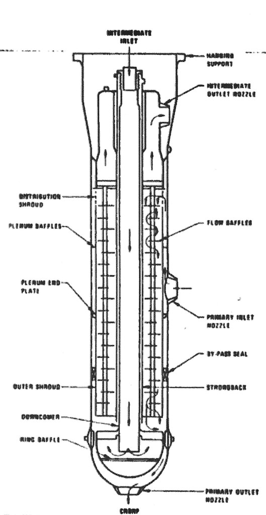
Figure 30 CRBRP IHX
In view of the fact that sodium coolant presents a benign environment for the metals that contain it; the removable bundle feature presents a cost savings opportunity that should be capitalized upon, as it was on CRBRP. Since it is proposed (section 8) to put an auxiliary tube bundle in the IHX for the PRACS and this bundle may be of a helical coil design, any requirement for tube bundle removability faces another obstacle.
It happens that the designer of the CRBRP IHXs, Foster Wheeler, was commissioned to design an IHX with 1000 MWth thermal duty in the late 1970s as a part of exploratory studies for a follow-on plant to CRBRP. The design was required to have a primary side pressure drop of no greater than 10 psid. The resulting design shown in the figure below had 4284 1 1/4 in. diameter tubes on a 1 7/8 in. triangular pitch. The unit incorporated a 17 MWth helical coil Primary Reactor Auxiliary Cooling System (PRACS) in the inlet plenum, had an overall length of 65.6 ft., a maximum diameter of 13 ft., and weighed 298 tons.43
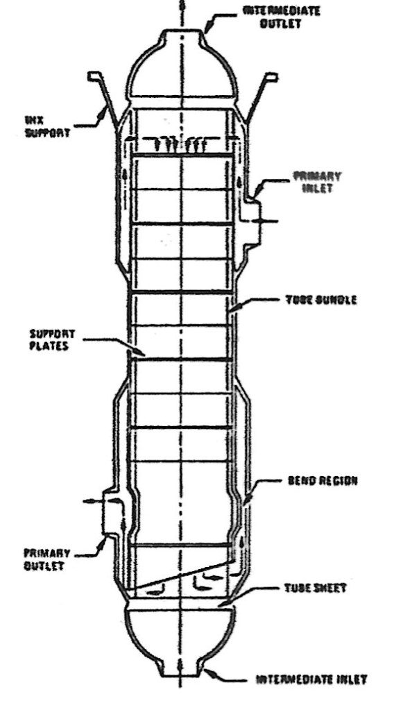
Figure 31 1000 MWth IHX
Note that this design looks like a more ordinary heat exchanger compared to its CRBRP equivalent with the shell side inlet and outlet on the side, tube side inlet and outlet on the bottom and top, the inlet plenum distinct from the outlet plenum, and no central downcomer. The PRACS coil would be in the upper part of the primary side inlet plenum, with a thermal center about 14.5 ft. below the top of the unit. The paper cited above reported on a trade off between three designs having different primary side pressure drops. Only the high pressure drop unit was deemed to be transportable over land — the other two requiring barge shipment. A 1500 MWth unit would have a shell diameter approaching 16 ft., probably requiring barge shipment. This single fact could be decisive in the selection of the number of primary loops for the plant, particularly in view of the interest in keeping primary side pressure losses at a minimum. A four loop plant with 750 MWth IHXs may turn out to be preferable possibly dependent of the site selected. Whether the reactor vessel is barge transported or fabricated on site would influence this decision. Other factors influencing this decision are material selection (austinitic vs. ferritic steel), advances in heat exchanger technology since 1978, and the LMTD across the IHX tubes.
In section 8, it is proposed that a key system for decay heat removal in the “design approach” involves a committed separate coil at the top of the IHX. This system is called the Primary Reactor Auxiliary Cooling System or PRACS. The thermal center of the PRACS coil in the IHXs should be 30 ft. above the thermal center of the core to ensure abundant natural circulation. In Appendix 2E, it is shown that with a 30 ft. driving head this natural circulation flow is about 14% of full flow at a reactor ΔT of 324°F and will vary as the square root of the ΔT.
The requirement that the PRACS coil be 30 ft. above the thermal center of the core leads to the IHX being above the Reactor Vessel (RV). The sodium level in the RV is about 15 ft. above the core thermal center (see figure 21) and the middle of the PRACS coil is about 15 ft. below the top of the IHX, so the IHX would extend about 30 ft. above the top of the RV. This constitutes a departure from previous sodium cooled reactor plant designs where the free sodium level in the RV was the highest point reached by the sodium in the PHTS. (It appears from the drawing above that the JSFR-1500 design may have located the IHXs slightly above the RV.) This comes as a consequence of both shortening the RV and incorporating PRACS into the design.
During normal operation, this arrangement is not a problem since the RV cover gas would be pressurized to about 15 psig. However, during refueling operations, the sodium freeze seal in the rotating plus must be melted to permit head rotation, so the RV pressure must be reduced to atmospheric. Thus, the top of the IHX PHTS sodium would be about 25 ft. above the RV sodium level, and a vacuum must be drawn at the top of the IHX PHTS sodium when the plant is shutdown for refueling.
Since the IHX will be the highest point of the PHTS, entrained gas will tend to collect there. With RV pressure of 15 psig, the IHX pressure would be slightly above atmospheric and the IHX could be vented to the Radioactive Argon Processing System (RAPS) (see Section 12) or it could be vented to a convenient place such as the overflow vessel. When the RV is depressurized during refueling, it will be necessary to pull a vacuum on the IHX to keep it filled. This could be accomplished using the RAPS compressor or more likely, by some other convenient special purpose device.
It is clear from the above that while it is possible to achieve a 30 ft. thermal driving head between the core and PRACS thermal centers, the IHX cannot be elevated much further without simultaneously lengthening then RV. Since the IHX length is 65.5 ft and there must be 10 ft. clearance below the IHX to accommodate the IHTS inlet piping, it will be necessary for the basemat elevation below the IHXs to be about 15 ft. below the RV basemat elevation. With the containment design proposed in this “design approach”, this does not introduce any particular problem. The thermal center of the main IHX tube bundle would be 13.5 ft. above the thermal center of the reactor core, which would be sufficient for natural circulation it the PHTS loops, if such natural circulation were desired.
A final modification to the HTS that needs to be incorporated is to extend its load following capability down to 15% in order to provide maximum load following capacity for the plant. This kind of requirement would be applied to cause the plant to be compatible with a power grid having extensive renewable energy generating capacity. One challenge would be to develop a pump power supply and an electric motor capable of running at very low speeds. This should not be a problem for the EM pumps in the primary system and if it proves to be impractical for centrifugal pumps in the intermediate system, they could also be changed to EM pumps. In fact, EM pumps would likely be preferred for the IHTS so the plant transient response would be matched between the PHTS and the IHTS. Centrifugal pumps can have a long coastdown following trip that does not apply to EM pumps.
he capability of the steam plant, particularly the turbine generator, to operate at these low power levels needs to be assessed. Another issue that could crop up at very low flows could be competition from natural circulation. As is shown in Appendix 2E, the natural circulation flow with a 13 ft. thermal centers separation between the core and the IHXs would be 9.3% at full system ΔT. To operate the plant at 10% power may require the primary pumps to be shutdown and may lead to a reduced reactor ΔT if the natural circulation flow turns out to be greater than predicted – a likely result. While this is not impossible to design for, it likely would be desirable to accept 15% as the plant minimum for load following purposes.
To sum up the conclusions as they pertain to the JSFR-1500 HTS design:
• The top entry concept may be incompatible with open vessel refueling but would probably be okay for the single rotating plug concept where the entry would be through the fixed portion of the head.
• The centrifugal pump in the primary system should be replaced with cold leg EM pumps. The EM pump could be integrated into the IHX or installed in the cold legs. If the cold leg is split, it may be desirable to install a pump in each leg for a total of four primary system EM pumps.
• The double walled elevated piping is unnecessary when the centrifugal pump is replaced with an EM pump and its elimination should be considered. However, if double walled primary system piping can be used as a basis for elimination of the double ended primary system pipe break from the design bases, the double walled piping should be retained. In either case, piping that is not elevated would require guard protection.
• The hot leg piping diameter should be increased above JSFR-1500 dimensions to 60 in. and the cold leg to 48 in.
• Primary sodium should be on the shell side of the IHX.
• The reactor vessel design needs revisiting assuming single rotating plug or open vessel refueling.
• The IHTS & steam generator designs are suspect but probably not too important from an economic point of view. Replacing two double walled steam generators with four helical coil steam generators may be more economic and could provide more flexibility of operation.
• The DRACS may only be applicable to a top entry system, would not be appplicable for open vessel refueling, and may require an increased reactor vessel diameter to adapt to the single rotating plug in the “design approach”.
• An overflow vessel should be included in the design as a means to reduce reactor vessel height.
• The absence of cutoff valves in the IHTS should be revisited from the point of view of controlling possible sodium water reactions.
• The use of ferritic steel in the PHTS is desirable, particularly as tube material in the IHX, and if compatible with the selected parameters should be adopted, at least in part.
Otherwise, the two loop concept with two cold leg pipes per loop and close-in components with an elevated IHX with split cold leg piping appear attractive. A possible layout of the HTS major components and the PHTS piping is shown in the figure below. The inside plan dimensions of the containment building in this diagram are 80′ by 120′. There could be a down loop in each of the two RV outlet legs within the reactor vault before the piping enters the IHX vaults. (The RV vault wall would be moved outward.) Similarly, the IHX outlets could be vertical with the EM pumps in the vertical leg. If it proves necessary to provide down loops in the cold leg piping, assuming the top of the diagram is north it would be necessary to move the IHXs east about 10 ft. and correspondingly increase the size of the containment building. The turbine building would adjoin the south side of the steam generator building to permit the Steam Generators to be on an outside wall.

Figure 32 Proposed HTS layout
An alternative layout that would require evaluation would be to locate the IHXs north and south of the RV. Doing so would shorten the distance between the RV and the IHXs and would enable the four cold legs to be symmetric. The main problem with doing this is it would interfere with the refueling cell since the IHXs are much longer than the RV and would extend to the roof of the cell. The JSFR-1500 is a close coupled north-south layout with the RV outlet nozzles feeding directly to the IHX inlets (see Figure 25). How such a scheme accommodates thermal expansion would require input from the designer. Also, tube plugging would be challenging in a unit adjacent to and not shielded from the reactor.
It is necessary to enumerate the Cost Saving Measures of the proposed HTS system in comparison the CRBRP.
28. The elevated unguarded PHTS piping concept is abandoned, permitting greatly reduced containment volume.
29. Centrifugal pumps are replaced with EM pumps in the primary circuit.
30. Two primary loops down from three.
31. Elimination of requirement for pony motors on PHTS and IHTS pumps
32. Check valves are eliminated from PHTS.
33. Guarded PHTS piping eliminates need for liners on PHTS vaults.
Parameters selection
An important part of HTS design is the selection of primary and intermediate system hot and cold leg temperatures and steam conditions, including feedwater inlet temperature, steam pressure, and superheat. HTS parameters selection involves a compromise between the quest for high thermodynamic efficiency and the limitations imposed by the core materials, particularly the fuel and inner blanket cladding material. By and large this compromise has already been made on CRBRP with the resulting selected primary system hot leg temperature of 995°F. So long as the cladding material remains austenitic, the CRBRP result remains applicable modified upward somewhat by the proposed thermal-hydraulic improvements suggested in Appendix 2D and section 6.
Another consideration which pertains to this issue is the steam generator. For the “design approach”, the Superphénix steam generating system has been identified as the reference design. The reasons for this are simple – Superphénix was one of the few LMFBRs incorporating a once through steam generator of a commercial design which actually accumulated some experience that was essentially trouble free. There are three good reasons for being especially careful with the steam generator system in a LMFBR. First, the consequences of a water to sodium leak are significant. Second, historical experience with LMFBR steam generators has not been good. Third, the duty a once through steam generator is exposed to is challenging.
Consider figure 29 above on the temperature profile of a once through steam generator. This profile actually uses Superphénix parameters. At the feedwater inlet, the temperature across the tubes is nearly 200°F, placing the inner wall of the tubes (the water side) in tension and the outer wall in compression. A similar high ΔT occurs when boiling is complete at the onset of superheating. In the boiling region the water side tubes are constantly being exposed to wetting and drying as bubbles form and break away from the tubes. This wetting and drying will cause large swings in the water side surface temperature of the tubes exposing them to fatigue and possible failure. It was concern over these issues that led the CRBRP designers to select a recirculating system, which didn’t eliminate the problems but did ameliorate them somewhat.
Although the Superphénix system was trouble free for about five years of operation, there is no guarantee that the Superphénix steam generating system will survive a 40 or 60 year plant lifetime but unfortunately, aside from the recent Russian experience at BN-600, Superphénix is the best experience available for a commercial-grade steam generator.37 It is for this reason that the Superphénix steam parameters are selected for the purposes of this study. Using the Superphénix steam side parameters essentially locks in the IHTS parameters but not the PHTS parameters. Superphénix PHTS, IHTS, and water/steam side parameters are presented below:
| | Hot Leg | Cold Leg |
| PHTS | 1013°F | 743°F |
| IHTS | 977°F | 653°F |
| Water/steam side | 914°F | 459°F |
Table 1 Superphénix HTS parameters
The BN-600 experience with their steam generators is too compelling to be ignored. As of the end of 2018 they had not experienced a steam generator leak since 1991. The BN-600 steam pressure is about 2015 psig and temperature is about 944°F. BN-800 is about 1970 psig with steam temperature of 914°F. At a minimum, some sort of collaboration should be attempted and wholesale procurement might be considered. Such a path could lead to changes in the parameters and reconsideration of the decay heat removal system since the BN-600 steam generating system involves separate evaporators and superheaters (as well as reheaters).
Back to Superphénix, the ΔT on the hot side of the IHX is 36°F while the ΔT on the cold side is 90°F giving a LMTD of 59°F across the IHX. These rather strange numbers are partly the result of efforts to minimize the size of the IHX tube bundle which is located within the pool while taking advantage of the highest reasonable temperature that the fuel system could deliver. For a loop type plant, the IHX tube bundle can be allowed to grow without excessive economic penalty. A constant ΔT across a tube bundle yields the most efficient utilization of tube surface area. If a constant 40°F temperature drop were to be adopted across the IHX, the PHTS hot and cold leg temperatures would become 1017°F and 693°F respectively for a PHTS temperature rise across the reactor of 324°F. This compares with a 265°F increase across the CRBRP reactor, a 22% increase. For a scaled up core, the 22% greater ΔT translates into about 22% less primary system flow and 22% lower flow velocity in the PHTS reducing pressure drop by 39%. For all the reasons detailed in Appendix 2D, this is a highly desirable outcome. Total primary system flow for these parameters would be about 225,000 GPM requiring each pump to be capable of delivering about 56,250 GPM. The primary and intermediate flow rates would be the same. The proposed parameters are repeated in the table below.
| | Hot leg | Cold leg |
| PHTS | 1017°F | 693°F |
| IHTS | 977°F | 653°F |
| Water/steam side | 914°F | 459°F |
Table 2 Proposed HTS parameters
Before leaving this subject there is another matter in need of discussion. Superphénix was not the only plant where the PHTS ΔT was greater than the IHTS ΔT. In fact, on CRBRP, the ΔT across the hot side of the IHX was designed to be 59°F while on the cold side it was 79°F. This raises the question of why the PHTS and IHTS flow rates weren’t equalized on CRBRP. The answer is transients. On the occasion of a reactor trip the reactor power immediately drops to the neighborhood of 6% and continues down to below 2% after one minute. Meanwhile, even if the primary pumps are tripped immediately when the reactor is tripped, primary flow will be greater than decay power because of pump coast-down. The PHTS pumps, being centrifugal, have a significant moment of inertia and it required 20-40 seconds for them to coast down to the 10% flow which would correspond to the pony motor flow rate. During this period, the primary system flow rate considerably exceeds the decay power from the reactor core with a resulting sharp decrease in hot leg temperature. This sharp temperature decrease exposes hot leg components to stress. It was primarily for this reason that the CRBRP PHTS temperature rise across the reactor was limited to 265°F even though IHTS ΔT was 285°F. The smaller the PHTS ΔT, the less severe will be the transients.
For the design approach being advocated herein, this consideration is not germane since EM pumps are being proposed for the PHTS system. Indeed, the ability to reduce transient response is one of the reasons for adopting EM pumps for the PHTS. When a reactor trip occurs, the EM pumps can be programmed so that PHTS flow rate matches reactor decay power. Fairly soon after trip (probably immediately), natural circulation will assume the responsibility for core cooling and the EM pumps can be shut down.
endnotes
36 IAEA-TECDOC-1531 2006, page 243
37 Ichimiya, M.; Mizuna, T.; Kotaki, S.; The Next Generation Sodium Cooled Fast Reactor Concept and its R&D Program; Nuclear Engineering and Technology, Vol. 39, Number 3, June 2007
38 Ota, H.; Katsuki, M.;Taguchi, J.; Fanning, A.W.; Doi, Y/; Nibe, N.; Ueta, M.; Inagaki, T.; Development of a 160 M3/min. Large Capacity Sodium Immersed Self-Cooled Electromagnetic Pump; Nuclear Science and Technology, Vol. 41, No. 4, pp. 511-523, April 2004.
39 Fanning, A. et al, Giant Electromagnetic Pump for Sodium Cooled Reactor Applications, IEEE, 2003
40 The figure is for illustrative purposes only. A more exact figure would show curved lines for all but the saturation line.
41 In fact, a 70 MW hockey stick unit, which was the planned CRBRP configuration, was tested at ETEC, but it was tested in the once-through mode.
42 R. W. Devlin, J. D. Bresnahan, WARD, FFTF and CRBRP Intermediate Heat Exchanger Design, Testing and Fabrication, Procedings of the US/USSR Seminar on Problems of Design, Development, Fabrication, and Test of Breeder Reactor Components, Feb. 6-9. 1978, Los Angeles, CA
43 G. B. Brown, J. F. Cox, IHX Portion of Paper on Advanced Work on Pumps and Heat Exchangers, Proceedings of the US/USSR Seminar on Problems of Design, Development, Fabrication and Test of Breeder Reactor Components, Feb. 6-9, 1978, Los Angeles, California
44 There is more experience with the EBR-II steam generators but the design is not practically scalable.
