The decay heat removal system is a key component in the description of any nuclear plant since it addresses the very feature about nuclear power that differentiates it most from other sources of energy, viz. it is a heat source that cannot be fully shut down. When the control rods are inserted and the nuclear reaction is halted, radioactive fission products continue to generate heat that must be removed from the reactor. It is important to recognize that it was not the nuclear reaction but the decay heat that did the damage at Chernobyl, Three Mile Island, and Fukushima Daiichi. At the instant the nuclear chain reaction is halted, the decay heat energy is about 6.6% of full power, declining to about 1% after an hour.
The CRBRP steam generator auxiliary heat removal system has been mentioned twice before in this paper and this section will begin with a more complete description of that system in the interest of thoroughness on this important topic. The operative portion of this system is shown in the figure below. There are protected air cooled condensers (PACCs) that are supplied with steam directly off each of the plant’s three steam drums. Steam condensing in the protected air cooled condensers is returned to the respective steam drum by natural circulation. The PACC itself was designed to be cooled by blowers, two of which were powered by emergency diesel generators and a third by the plant battery. Each PACC had a design heat removal capacity of 15 MW or 1.5% of the plant’s full power. The SGAHRS was designed to operate with the pony motors in the PHTS and IHTS operating. The auxiliary feedwater system took suction from a protected water storage tank and one of the three auxiliary feedwater pumps was steam driven with the steam coming from any of the three steam drums. The system was designed so that a single PACC could remove 100% of the reactor decay heat so long as one auxiliary feed pump was operable. One hour after shutdown, the auxiliary feedwater can be secured.
Despite the fact that the system was designed for operation with pony motors and blowers, the designers were mindful of the desirability of preserving a natural circulation capability, and designed accordingly, maintaining the IHX thermal center above the core and the evaporator thermal center above the IHX. Six years after design activities had been launched; the capability of the SGAHRS to operate in the natural circulation mode was evaluated, and found to be more than adequate. A re-evaluation was performed in 1982 after the core design had been modified. The result was that following station blackout conditions with the turbine driven auxiliary feed pump operating, the primary flow leveled off at 3%, intermediate flow at 4% and recirculation flow at 11% in about three minutes after shutdown. Reactor Vessel outlet temperature never exceeds 1025°F, well within allowable margins.
This remarkable result was buried in section 5.7.5 of the PSAR under 5.0 “Heat Transport and Connected Systems” and 5.7 “Overall HTS Evaluation”. It did not appear in the Table of Contents anywhere. Its total length was slightly more than three pages and included just two figures. It cited two references45 46 that would have provided a more thorough description but included only a perfunctory summary in the PSAR. So it turns out CRBRP had station blackout capability long before Fukashima and it made just about no effort to capitalize on the accomplishment. The only way to explain this is that the CRBRP was designed before Fukashima when the importance of decay heat removal during station blackout was not fully appreciated.
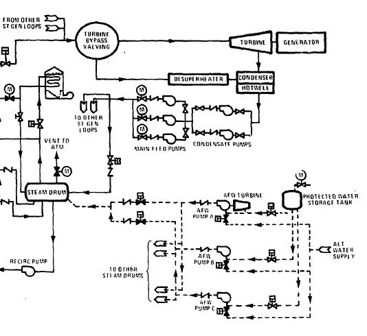
Figure 33 CRBRP steam generator auxiliary heat removal system and auxiliary feedwater system
In retrospect, there is no question the SGAHRS would have been more attractive had it been designed specifically for operation without electric power from the beginning, which it obviously could have been. The PACCs would have been natural draft with no fans and the pony motors, if they were still provided, would have had no safety significance. It seems likely that if the plant’s decay heat removal system was known to be operable during station blackout, other parts of the plant design would probably been effected, making it less reliant on 1E power. Eliminating the blower in the PACCs would probably have led to a larger PACC unit but little else. Since the system was totally closed, the only occasion it had for requiring any make up water was during the first hour of operation, primarily due to the sensible heat of the sodium inventory and the fact that the superheater would no longer be removing any heat. During this one hour period, relief/control valves would open on the steam drum so makeup water would be needed. A second auxiliary feedwater pump would probably have been steam driven. If the SGAHRS had been designed from the beginning for lights out operation, the CRBRP would have been one of the first commercial reactors to have had such a capability and it could have been a good advertisement for one of the particular merits of the LMFBR concept. This SGAHRS as it was designed did not satisfy the NRC, probably because it was dependent on the steam generating system, which was known from Fermi-1, the British PFR, and the Russian plants to have a record of questionable reliability. The project therefore proposed a second decay heat removal system, which the project called the Direct Heat Removal Service (which unfortunately shares the same acronym, DHRS, with the Decay Heat Removal System) shown in the figure below.

Figure 34 CRBRP Direct Heat Removal Service (DHRS)
This system was a rather clever way to bring preexisting capability to bear to strengthen the reactor decay heat removal system. Since the EVST may be loaded with heat producing spent fuel, it is necessary to provide it with cooling that is reliably powered. The CRBRP DHRS borrowed upon this capability when needed. The only item added to the plant was an overflow heat exchanger and some connecting piping that enabled the plant operator to shift the reactor decay heat load to the EVST air blast heat exchangers that were already in the design. There may also have been a capacity upgrade of the NaK pumps and the air blast heat exchangers. Each air blast heat exchanger was capable of removing 5.5 MW so the two operating together would handle the core heat load after about one hour following shutdown.
Numerous other means for decay heat removal have been used or proposed, particularly in the years since CRBRP was cancelled. The proposed JSFR-1500, shown in the figure below,47 design is very typical. There are two systems, a Direct Reactor Auxiliary Cooling System (DRACS) and a Primary Reactor Auxiliary Cooling System (PRACS). The DRACS involves a single cooling coil which is immersed through the head inside the reactor vessel. NaK flows through the coil and naturally circulates to an air cooled heat exchanger located high above the reactor. The PRACS involves independent coils in each of the two IHXs again containing NaK and again naturally circulating to an air cooled heat exchanger. Each of these three systems is capable of removing all the decay heat from the reactor independent of any electric power.
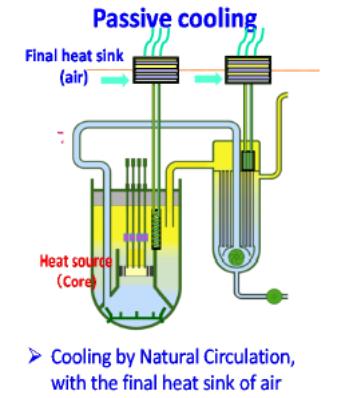
Figure 35 JSFR-1500 decay heat removal concept
A variant of the PRACS can be found on the Korean plant design KALIMER-600 shown in the figure below.48
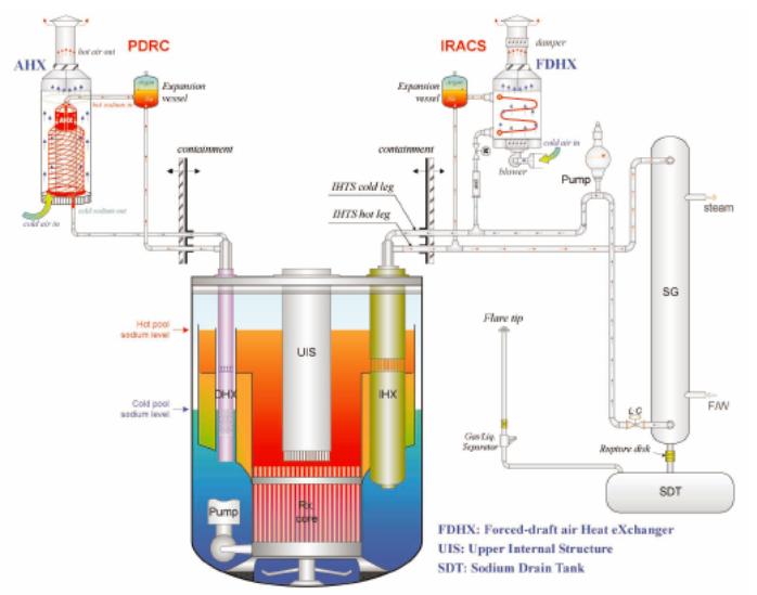
Figure 36 KALIMER decay heat removal concept
KALMIR-600 uses a DRACS which they call a passive decay heat removal circuit and an Intermediate Reactor Auxiliary Cooling System (IRACS) that taps off the intermediate loops and is cooled by a forced draft heat exchanger. The Korean designers probably felt that having one circuit, the passive decay heat removal circuit that is totally cooled by natural circulation would be sufficient and it would be easier to control a forced draft system. There is no reason why the IRACS system couldn’t be designed with air heat exchangers that are cooled naturally. IRACS with EM pumps is the decay heat removal system installed in the Russian BN-800.
Among the other systems that have been proposed is one that naturally circulates air by the guard vessel of pool type plants. Variations of this concept have been used on PFR in the UK and Phénix and Superphénix in France. They are generally somewhat marginal in their performance and depend on the large inventory of sodium within the pool to slow the temperature rise before the guard vessel cooling can keep up with the decay heat. Since the design approach that is being proposed purposefully avoids a large sodium inventory, this sort of system would likely not be attractive.
Just about any system that is 100% redundant, totally passive, can operate without electric power (including instrumentation), and is independent of the steam generating system would be better than the world’s fleet of LWRs to date. Of the systems shown above, the DRACS would probably not be compatible with open vessel refueling, but it would be compatible with the single rotating head concept, which is another advantage of the single rotating head system over the open vessel system. For the concept presented here, any DRACS would be located as high in the RV as possible (below the minimum safe level) and its primary side outlet would be connected to a downcomer that would penetrate the core support cone. The maximum thermal driving head would be on the order of 10 ft. Another problem with DRACS is there doesn’t seem to be any way to avoid a considerable bypass flow in the RV from outlet to inlet without some sort of valve. Such a valve could be pressure activated by the PHTS pumps, but such a solution could interfere with load following at low power levels when PHTS pump discharge pressure is at a minimum. A creative solution to this problem is an attractive candidate for an R&D effort, and is included in Appendix 9.
From a reliability point of view, the difference between the PRACS and the IRACS is small assuming the IRACS is cooled by a naturally circulating air heat exchanger. The IRACS is more straightforward, not requiring a separate coil in the IHX and using sodium to the air cooled heat exchangers in place of NaK. However, with IRACS the IHX tube bundle is part of the decay heat removal circuit requiring that the thermal center of the IHX tube bundle be elevated well above the reactor core – possibly in the range of 30 ft. As was discussed in Section 7, this could lead to a requirement to lengthen the RV so as to enable circulation in the PHTS during refueling operations. Moreover, it would be necessary to ensure that the sodium in the air heat exchanger is kept molten during normal plant operation when the IRACS is not in use. This would probably be best accomplished by maintaining a small flow through the air heat exchanger with some kind of a damper on the air side that is kept shut and limits air flow. IRACS also results in the entire IHTS becoming important to safety, at least up to and including the IHTS isolation valves, if such valves are present. These undesirable features have the result of making the PRACS the more attractive option. If necessary to achieve belt and suspenders diversity and redundancy, both PRACS and IRACS or PRACS and DRACS or DRACS and IRACS could be deployed together on the same plant, accepting the economic penalties described above. Another option would be to have two 50% PRACS coils within each IHX.
It would be desirable to have a diverse system available. For this purpose, the Overflow Heat Removal Service (OHRS)49 of CRBRP certainly would be diverse and would bring with it all the benefits previously stated. Because of its ready controllability and ease of operation, the OHRS would probably be the preferred means for routine decay heat removal during refueling or other routine shutdowns. Because of the need to prevent freezing in the ultimate heat sink, it would be necessary to use the NaK cooled OHRS to reduce the sodium temperature to the 250-300°F range that would probably be preferred for refueling operations. (This temperature range would apply to open vessel refueling but not necessarily to the single rotating plug option.) It would also be preferable for the EVST to be capable of natural circulation to its Na/NaK heat exchanger and the associated NaK system to naturally circulate. In addition, the NaK to air heat exchangers should be capable of functioning without air blast fans, i.e. natural draft. When used for this service, the EM pumps providing the overflow should be designed for a minimum flow rate of about 1% of full PHTS flow or about 2250 GPM.
A brief treatment of the thermal capability of these two systems needs to be included in this discussion. For the case of CRBRP, the thermal capability of each of the SGAHRSs was 15 MW. Since the SGAHRS was designed for one system to be out of service followed by a single failure, each of the three SGAHRSs could handle the entire decay heat load of the plant. This 15 MW turns out to be an overestimate of the heat load for three reasons. First, the SGAHRS was designed for CRBRP stretch conditions, which were 1121 MWth as opposed to design conditions of 995 MWth. Second, the designers always were holding station blackout as an option, which tended to lead to additional capability than required for the reference case. Third, SGAHRS had to deal with the sensible heat of the HTS that was above the temperature of the steam drum. This imposed a considerable additional load on the system during the first hour after shutdown. A better indicator of the amount of decay heat removal capability would be the CRBRP OHRS, which was designed for 11 MW.
Another benchmark can be drawn from the Foster Wheeler 1000 MW IHX discussed in Section 7. That unit was required to have a PRACS coil capable of removing 17 MW. That was probably based on a 3000 MW three loop plant design, later called the Large Scale Prototype Breeder. Assuming the single failure criterion was applied would lead to a 34 MW decay heat load for the 3000 MW design, which would be consistent with scaling up the CRBRP OHRS to 3000 MW. Since the single failure criterion would apply to the “design approach”, and there are just two IHXs, each PRACS coil as well as the OHRS would be obliged to have a 33-34 MW capability.
Summarizing, the proposed decay hear removal system consists of two totally passive PRACS, each capable of removing 100% of the reactor decay heat and an OHRS dumping its heat to two naturally circulating EVST heat exchangers. Additionally, since the PHTS and IHTS will naturally circulate, heat can be dumped to atmosphere from the steam generators with feedwater being supplied by steam or motor driven auxiliary feedwater pumps, although this circuit would not be safety grade. A de-superheater would probably be required for the steam driven feedwater pumps and some form of pre-heat would be needed for the auxiliary feedwater, since extraction steam would not be available. If this configuration fails to provide adequate reliability, since there are four IHTS loops, the two PRACS could be exchanged for four 50% IRACS at an associated capital cost penalty or, alternatively, a DRACS could be added, for the single rotating plug concept.
The elimination of the requirement for the IHTS and SGS to be important to safety is considered CRM 44. Whether PRACS is less expensive than SGAHRS is not assured but since it does not require separate evaporators, superheaters, and steam drums, and it does not require the SGS and IHTS to perform a safety function, it would certainly appear to be.
endnotes
45 Lowrie, R.R.; Severson, W.J.; A Preliminary Evaluation of the CRBRP Natural Circulation Decay Heat Capability, WARD-D-0132, 1978
46 Severson, W.J., Summary Report on the Current Assessment of the Natural Circulation Capability with the Heterogeneous Core, WARD-D-0308, Feb. 1982
47 Progress on Fast Reactor Development in Japan, H. Ohira, N. Uto, Meeting ofm the Technical Working Group on Fast Reactors, June 20-22, 2012
48 Kwi-Seok Ha, Hea-Yong Jeong, Comparison of the Decay Heat Removal System in the Kalimer-600 and DSFR, Nuclear Engineering and Technology, Vol. 44, No. 5, June 2012.
49 The term “Overflow Heat Removal Service” is more descriptive than “Direct Heat Removal Service”, and will be used in the balance if this paper.
