A Fuel form
The precedent for the use of metal fuel in the early reactors was established by the production reactors, which used metal fuel clad in aluminum. Aluminum was chosen as a clad because of its availability, thermal conductivity, and low thermal neutron absorption cross section. Aluminum is not suitable for use above about 400°F, so zirconium with its tolerance for high temperatures and its low thermal neutron absorption cross section was selected for the early thermal reactors. For the case of fast reactors where thermal neutron absorption is not an issue, stainless steel with its excellent strength at high temperatures, its compatibility with sodium, and its relatively low cost proved to be the preferred cladding.
As early as the late 1950s, the desirability of changing the metal fuel form to the oxide began to emerge. First, the metal form did not perform well with burnup. With burnup as low as 10,000 MWD/MTU or about one atom percent, the fuel swelled and became spongy with fission gas buildup, partly as a result of its poor creep strength. Second, the metallic form is chemically reactive and difficult to handle. Some cladding materials considered as alloying agents to improve its creep strength were found to chemically react with uranium. Third, the metal exists in several different phases, which change with temperature, limiting its application to temperatures that are lower than would be desired in commercial sodium cooled fast reactors. Fourth, the metal is more difficult to reprocess than the oxide, adding steps that increase reprocessing costs. Fifth, the LWR industry was moving to oxide fueled systems and if synergies were to be achieved between the two classes of reactors in reprocessing and fabrication, it would be necessary for the breeders to use the same fuel form. Sixth, and perhaps of greatest significance is the Doppler Effect.
In the early 1950s, it was thought that Doppler wasn’t too significant in fast reactors since the spectrum was well above the resonance region and the neutron flux in that region is relatively low particularly in small reactors. Illustrative of this mindset, a text book on fast reactors initially published in 1961 contains the following statement: “The Doppler Effect is small and of minor importance in fast reactors”.1 As core calculations were beginning on large, oxide fueled fast reactors, it was found that there was a small but not insignificant neutron population in the resonance region that could result in a significant contribution from the Doppler Effect.2 This is due to the softening of the spectrum caused by oxygen in the fuel pellets, the higher flux levels associated with larger sized, lower enrichment cores using a less dense fuel, and the poor thermal conductivity and higher operating temperature of the oxide. The melting point of UO2 is about 5150°F. and PuO2 is about 4400°F. The melting point of the mixed oxide, intermediate between these two extremes, declines up to 150°F with burnup, probably due to the buildup of fission products. At peak power levels, the oxide temperatures are not far below these limits, particularly when uncertainties are applied.
About the same time that interest in the use of oxide fuels was emerging, in 1955 the EBR-1 reactor experienced a partial meltdown caused by inward bowing of the fuel assemblies. The inner surfaces of the fuel ducts ran hotter than the outer surfaces, causing them to bow inward with increasing power. This inward bowing effect was a positive power coefficient which led to an excursion that terminated in a meltdown of approximately 40% of the core. This accident3 led reactor designers to focus on the importance of the prompt reactivity coefficients, and to recognize that as many of the reactivity coefficients as possible needed to be negative.
Contributing to this situation is the delayed neutron fraction. The delayed neutron fraction, β, for the isotopes of interest in reactors, both LWRs and LMFBRs, are given below:
| isotope | β |
| U235 | 0.0073 |
| Pu239 | 0.0023 |
| U238 | 0.0157 |
Table 6 Delayed neutron fractions
Assuming a fast fission factor of 1.03 to account for U238 fissions gives a β of 0.0078 for LWRs. With plutonium fuel and U238 accounting for about 20% of all reactor fissions, the LMFBR β would be calculated to be 0.0050, considerably lower than for LWRs. It turns out that the β for LMFBRs is actually lower still. The determination of β for the reactor needs to account for the importance of the delayed neutrons produced. The “importance” of a neutron is a measure of the likelihood of that neutron participating in a subsequent fission. If it more likely to be absorbed than to cause a subsequent fission, its “importance” will be low. This is particularly germane in a fast reactor where core heterogeneity is enhanced by the presence of internal, radial, and axial blankets. Once the importance has been accounted for, the result is known as beta effective or βeff. Since a good fraction of the U238 fissions occur in the radial and axial blankets where their importance is low, βeff for LMFBRs is better approximated by 0.003 – 0.004. For the case of CRBRP with a heterogeneous core design, βeff was calculated to be 0.0034. This smaller margin to prompt criticality further supports the argument of the need to provide the reactor with stability enhancing negative prompt reactivity coefficients.
Caught in the middle of this transition was the Fermi-1 reactor. In the mid 1950s when the plant was being designed there was early indication that the oxide fuel form could be superior to metal fuels but the magnitude of the Doppler Effect was unknown and the designers chose metal for the initial core to benefit from the negative reactivity coefficient resulting from thermal expansion of the fuel. For a small core such as Fermi-1, thermal expansion is a somewhat more important factor than for larger cores. It was also known that a higher breeding ratio and higher power density could be achieved using metal fuel. Sufficient quantities of plutonium were not available at the time for the initial core loading of the Fermi reactor so 25.6 wt. % enriched uranium was therefore selected for the initial fuel load. The metal fuel was in the form of pins alloyed with 10% molybdenum which tended to stabilize the uranium phase to the γ form which remained stable over the range of temperatures of interest to the Fermi-1 designers. Moreover, the alloying with molybdenum improved the creep strength of the uranium over that of the pure metal. Although alloying penalized the breeding ratio somewhat, its advantages were considered more important than its disadvantages.
Nonetheless, concurrent testing that was being performed in the Materials Test Reactor (MTR) showed that even with alloying; the maximum allowable burnup in Fermi-1 with this fuel would be about 10,000 MWD/MTU, which corresponds to about 1 a/o. MTR data predicted that in the hotter regions of the core near its center, burnup limitations as low as 0.6 a/o would need to be imposed. Because of all these impracticalities, it was planned to replace the Fermi-1 core eventually with a Pu/U mixed oxide core with a predicted breeding ratio of 1.28.4 Unfortunately, because of the problems the plant experienced with its steam generators and the partial melting incident, core replacement never occurred.
By the early 1960s, it became clear that if the LMFBR concept were to be successfully commercialized, it would be necessary to utilize oxide fuels and achieve burn-ups of at least 100,000 MWD/MTU. Several questions presented themselves. The fissioning process would generate fission gas within the fuel pin. This fission gas needed to be accommodated with some sort of gas plenum, expected to be about 3-4 ft. long. This plenum could be located either above or below the axial blankets or a combination of both above and below. Would the gas successfully transport out of the fuel pellet, through the fuel and axial blanket regions into the plenum? Would the fuel pin be sufficiently strong to accommodate the fission gas pressure? Would it be better to vent the fission gas into the reactor cover gas and remove it there?
In furtherance of the objective to explore the benefit to be obtained from the Doppler Effect, the Southwest Experimental Fast Oxide Reactor (SEFOR) project was initiated early in 1964. The 20 MWth SEFOR project was a joint effort funded by the AEC, a group of interested domestic electric utility companies, and included international participation through the Karlsruhe Laboratory in Germany. Completed in May, 1969, its primary objective was to demonstrate and measure the Doppler Effect in a LMFBR. It turns out that the SEFOR project demonstrated several additional concepts important to LMFBR engineering, some of which are treated in this monograph.5 The SEFOR reactor was provided with a control scheme that allowed super-prompt critical reactivity excursions in order to demonstrate the reactor behavior under extreme transients and the effect of Doppler in mitigating these transients.
While SEFOR construction was underway, a new and unexpected fuel problem arose. The phenomenon of stainless steel swelling at doses beyond 1022 n/cm2 was first reported in 1967.6 The phenomenon is apparently caused by a super-saturation of point defects, leading to voids collapsing into agglomerations producing internal strain in the material. When it was first observed, there was some evidence that it could lead to as much as 10% strain at fluences of 1023 n/cm2. Since large LMFBRs will have flux levels as high as 1016 n/cm2-sec, the onset of swelling could occur at two months of operation. In addition to producing elongation of the fuel pins, since the fluence tends to be greatest at the core centerline, the interior sides of the fuel ducts receive a greater fluence than the exterior causing the assembly to tend to bow outward at the ends. If the fuel assembly is restrained horizontally, as it certainly must be the bowing results in a stress, which is relaxed by creep, which may be caused by temperature alone or be enhanced by radiation.
In 1963 the phenomenon of neutron embrittlement on stainless steels from neutron irradiation was first reported.7 The phenomena associated with embrittlement are closely related to swelling. As the swelling approaches 20%, the strength of stainless steel drops precipitously and the material becomes brittle. This embrittlement is believed to be due to micro-fractures between voids and other dislocations in the crystal structure aligning perpendicular to any applied stress once the swelling reaches a critical level. Embrittlement may limit the ultimate exposure of fast reactor fuel to something in the 200,000-300,000 MWD/MTU range corresponding to about ten years of residence in the core.
By the mid 1960s, the unexpected fuel phenomenology produced a somewhat predictable effect. Throughout the LMFBR design community there emerged great activity focused on testing of fuel in order to get the best possible characterization data. By the time the CRBRP project was underway, a consensus had emerged that 20% cold worked 316 stainless steel was sufficiently resistant to swelling that it could be used with reasonable confidence for exposures up to a peak of 150,000 MWD/MTU with average burnup of 80,000 MWD/MTU. This was sufficient for CRBRP requirements so it was selected as the reference material for both the clad and the ducts.
As has been described earlier, there has not been much meaningful activity in breeder reactor development since the cancellation of CRBRP. However, two alloys have emerged that have promising applications as core assembly materials – D9 and HT9. D9 is an austenitic steel that is a variant of SS316 having slightly higher nickel and lower chromium with a small amount of titanium added. HT9 represents a more radical departure from the SS316 precedent – it is a ferritic alloy containing 12% Chromium and 1% Molybdenum. Both of these materials have enhanced swelling resistance as compared with 316SS and provide reasonable confidence that there are avenues available for performance improvement of steels that will enable the use of long lived cores.
A record high burnup level of about 35 a/o has been successfully reached with a six pin test assembly at BOR-60 while 260 pins have achieved 25-30 a/o burnup.8 All of this high burnup Russian experience has been accomplished with advanced alloy materials that are akin to but not identical with D9 and HT9.
Following the termination of the CRBRP project, technical representatives from ANL began resurrecting interest in the use of metal fuels in LMFBRs. The claim was that the low burnup issues had been resolved through the use of improved alloying materials and that metal fueled reactors offered more acceptable methods for dealing with ATWS events. However, even if it were possible to design a metal fuel that could reach the same burnup as an oxide, a very dubious possibility, the other five disadvantages of metal fuels stated at the beginning of this section would still apply, in particular the lack of any strong Doppler feedback. Moreover, there appears to be limited interest in metal fuels abroad – those countries that continue to develop the technology are doing so based on the use of oxide fuels. For these reasons, the design approach presented herein will be based on the use of oxide fuels with whatever cladding material offers the best performance at high burnup and is consistent with the identified operating parameters.
B Vented fuel
From the above discussion, it is clear that the fuel represents perhaps the most challenging single aspect of LMFBR design. The challenge is made no easier by the requirement that the fuel pin contain the fission product gases. The inert gases, krypton and xenon represent over a quarter of the fission product inventory so the pressure inside the fuel pin rises quickly with burnup. For the case of CRBRP, at a peak burnup of 10 atom percent, the pressure in the fuel pin was expected to be about 1000 psi. From the foregoing discussion it is clear that the damage being sustained by the cladding during reactor operation makes it ill equipped to deal effectively with the even higher pressures attendant with burnup greater than 10 atom %, but higher burnup is almost mandatory if the LMFBR is to have much of an opportunity of being economic. This raises the question of whether it is feasible to vent the fuel eliminating or greatly reducing the fuel pin pressure.9
Another incentive for venting the fuel pins is to reduce the length of the fuel assembly. Despite the fact that just 5 ft. 4 in. of the CRBRP fuel assembly is fueled, it is nearly the same length as a LWR fuel assembly and the pressure drop across the core is greater than is the case for a LWR. For CRBRP, core pressure drop was approximately 110 psi, about double that of a PWR. Partly this is attributable to the LMFBR core lattice being tighter and fuel assembly ducting with orifices to regulate flow to each assembly, but reducing the fuel assembly length by four feet would have reduced the core pressure drop on CRBRP by about 10-15 psi. Reducing fuel assembly height pays off in a corresponding reduction of both the reactor vessel and containment height. If EM pumps are used for the PHTS, there is an added incentive for reducing core pressure drop to compensate for the lower pumping efficiency of EM pumps.10
A third incentive for venting is to increase the fuel fraction of the fuel & blanket assemblies. If high burnup is attempted with unvented fuel, the cladding thickness must be increased to contain the higher fission gas pressure decreasing the volume available for fuel & blanket material. This is counterproductive to attempts to achieving long cycle time which require good breeding ratio thus a high fuel fraction in the core.
There are two options for fuel pin venting. One would be to collect the fission product gases within some chamber in the fuel assembly then carry away the gases using plumbing connected to each assembly. A second option would be to vent the gases directly to the coolant. Since the second option presents the easier solution, is less of a problem with refueling, and is potentially more reliable, it is worth considering first.
If fission product gases are vented to the coolant, it would be necessary to prevent sodium from flowing into the fuel pins during transients or reactor shutdown. Sodium chemically reacts with oxide fuel causing it to swell considerably. Prevention of such intrusion might be accomplished with some form of check valve or relief device that limits flow to one direction only. The fission product gases, if vented to the coolant would quickly accumulate in the cover gas where they could be removed by cryogenic distillation. Cryogenic distillation depends of the differing liquidus temperatures among the inert gasses. For the purpose of this discussion, the liquidus temperatures for inert gases of interest are presented below;
| He | -268°C |
| Ne | -246°C |
| A | -185°C |
| Kr | -152°C |
| Xe | -107°C |
Table 7 Boiling point of inert gasses
From the above, it is seen that cryogenic distillation should work for the fission gasses with either argon or helium as a cover gas, but it would certainly work better with helium. Neon is included in the list because it is the decay product of Na22 and will gradually build up in the cover gas if not removed. This probably doesn’t matter since Ne22 is stable. The xenon fission products do not pose much of a problem since the longest lived among them is just 5.27 days11, however Kr85 has a half life of 10.44 years. Kr81 has a half life of 2 x 10⁵ years, but little Kr81 is produced in fission. The means for dealing with krypton is one of the topics discussed in Section 12. Alternatively, the gas could be stored, at least allowing for Kr85 decay. About 25 ∙ 106 cm3 of fission gas at STP would be produced yearly by a 3000 MWth reactor, a tenth of which would be krypton with the balance xenon. Most of the xenon produced is stable or has a short half life and could be released. Assuming the krypton can be separated from the xenon, less than 100 ft3 of krypton at standard temperature and pressure would be generated yearly, which would be a manageable storage problem.
Other fission products that might find their way into the coolant would include iodine, which would rapidly combine with the sodium and be removed by the cold traps. One potential problem with venting the fuel assemblies into the coolant is likely not to be from the fission product gases or iodine but from Cs137. Cesium is an alkali metal with a melting point of 160°F and a boiling point of 1240°F, well below the temperature of the fuel when it is operating at full power. Although much of the cesium in spent fuel will combine with oxygen in the fuel, some will remain in its elemental state and be vented with the fission gases. It will then intimately mix with the sodium. It cannot be directly removed by chemical means, and will not be removed by the cold traps.12 With its 37 year half life, it will build up in the coolant and complicate plant maintenance. It was stated earlier in the paper that the Cs137 activation in the BN-350 reactor at end of life was 6-7 μCi/cm3. Venting the fuel to the coolant could lead to levels a hundred-fold higher, which would be equivalent to ~1000 μCi/cm3 and would lead to unacceptably high radiation fields in any areas carrying primary coolant. BN-350 ultimately dealt with their Cs issue by installing reticulated vitreous carbon filters, which reduced Cs137 concentration by a factor of 800.13 Carbon filters were first developed by ANL for use on EBR-II and require the sodium to be cooled to the 300-400°F. range. Such a device could be installed as a parallel stream on the line to the cold traps. Alternatively, some form of distillation could be used.
Venting the fuel to the coolant could create a licensing issue. Since the very beginnings of nuclear power development, a basic principle of design has been there are three barriers between the fission products and the environment: the fuel cladding, the primary system, and the containment. While not eliminating it altogether, venting the fuel to the coolant diminishes one of these barriers. One could argue that since the vented fission products are being continuously removed, the barrier is still, in effect, present, but the outcome of such an argument cannot be predicted with certainty.
A corollary fringe benefit of vented fuel is to eliminate the need for gas tagging of core assemblies. This, of course, raises another licensing issue. With vented fuel, it would become more difficult to locate a failed fuel assembly. One might question whether it is really necessary to locate a failed fuel assembly. Operating with failed oxide fuel has been demonstrated by testing at both EBR-2 and FFTF and operationally at BOR-60 without serious consequences but not over the long cycle lengths being advocated herein. The problem is that when sodium combines with UO2, the resulting compound has a lower density than the UO2. Although most if not all fuel material exposed as a result of a cladding breach is likely to be swept away by the coolant and wind up in the cold traps, it does not require much of a stretch of imagination to envisage sodium entrained fuel material blocking flow in the failed fuel assembly which could only be detected by the core exit temperature detectors.
An alternative to venting to the coolant might be to vent the fuel to a header that is collected and processed. One could envision the fuel pin vents being collected in some kind of a chamber at the top of each assembly then routed through channels in the upper internals structure, through the head, then to a processing station. This would not solve the failed fuel location issue since tagging would serve no purpose if the assemblies are continuously vented to a header, but it would eliminate the problem of cesium in the coolant. From a licensing perspective, this approach could well be considered worse than venting to the coolant since it would bring the fission products outside both the clad and the primary system boundary.
Regardless of the venting method used, if peak burnup in the vicinity of 30 atom percent is contemplated, fuel venting may be a necessity. Moreover, it improves neutronics performance and carries with it the prospect of shortening the reactor vessel and the containment by 4 ft., a worthy benefit.
C Nuclear design and Core Layout
The core design is, without question, the most important component of the total plant design. It drives the reactor vessel design and indirectly the refueling system design, the primary heat transport system design, and the containment design. When designing the plant, it should be the first design to be undertaken to a sufficient level of detail that confidence in its design is established. On the CRBRP project, that did not turn out to be the case as was described in Section 6. The point is that before any significant activity is undertaken on the plant design, there needs to be high confidence that the core design will not change radically.
If a reactor were to be designed with uniform enrichment, the resulting radial flux profile would be the fundamental mode of the wave equation in cylindrical geometry, which is actually the J0(r) Bessel function, but is reasonably closely approximated by the cosign function, which is the correct function describing the axial distribution. Although there is some neutron reflection at the core boundaries, it is not as pronounced as is the case for a LWR. Most of the power would be produced in the center of the core with relatively little production at the peripheries. As the core burned down, the flux would gradually move outward toward the regions where less burnup had occurred, but most of the burnup would be in the center of the core. Designers have combated this problem in LMFBRs by using higher enrichment assemblies in the outer core region, providing axial blankets above and below the core and a radial blanket with reflector/shield assemblies outside the radial blanket. The blanket assemblies are primarily intended to improve neutron economy and breeding and the shield assemblies are primarily provided to protect permanent structural components from excessive neutron fluence, but both also tend to reflect some of the neutrons back into the core. The result is a flatter flux profile across the core. The early CRBRP design was executed exactly this way. There were 109 inner fuel assemblies with fissile enrichment of about 16% and 90 outer fuel assemblies with a fissile enrichment of about 23.2%. The outer enrichment zone was surrounded by 150 radial blanket assemblies which occupied ~2 ½ rows. The fuel assemblies consisted of 217 0.23 in. diameter pins while the blanket assemblies consisted of 61 0.51 in. diameter pins. It was planned to refuel one third of the core annually. This core design is shown in the figure below where the shaded assemblies comprise the radial blanket and the outer enrichment zone comprises the outer two rows of the fueled core..
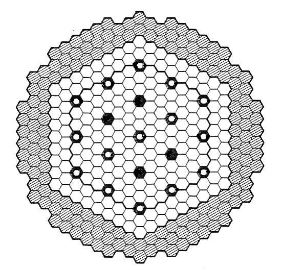
Figure 44 Early CRBRP two region homogeneous core design
When the CRBRP project was initiated in 1972, there was prepared a set of “Demonstration Plant Design Guidelines”, which were agreements between the government and utility company entities that were funding of the project on how the design would go forward. One of these design guidelines was a requirement that the plant be designed to operate with a minimum breeding ratio of 1.2. By the time the conceptual plant design had been completed in 1975, it was obvious that the breeding ratio guideline would not be met. The project office requested that some action be taken to address the issue.
Initially the prime contractor argued that the demonstration plant design guidelines would be met in the initial cycle if LWR recycled plutonium were deployed as the fuel rather than the low Pu240 plutonium that was planned to be used.14 The case wasn’t argued long since even with recycled LWR plutonium (which was not then available); the guideline could not be met beyond the initial cycle. To address the issue, the nuclear design personnel proposed a heterogeneous core design, selectively locating radial blanket assemblies in the high flux region of the core. At that time, they called this approach the “alternative fuel management scheme” or AFMS, since they wished to retain the homogeneous design as the plant’s reference design pending further evaluation of the AFMS, particularly its thermal-hydraulic performance. Although the resulting design had a somewhat higher fissile inventory, it satisfied the applicable demonstration plant design guidelines and offered some additional advantages. It reduced the number of fuel assemblies required and increased the amount of power produced by the blanket assemblies. Since fuel assemblies were expected to be considerably more expensive to fabricate than blanket assemblies, this was seen as having a direct economic benefit. AFMS also eliminated the need for two separate fuel enrichment zones. It was more effective at flattening the neutron flux profile than the two region concept and led to lower radial power peaking. The better flux flattening could be attributed to the better fine tuning available with the inner blanket assemblies. The neutron flux was somewhat lower due to the higher fissile inventory.
Fewer control rods were required primarily because simultaneous with the design of the heterogeneous core, it was decided to enrich the primary control assemblies. This was a sensible thing to do since it is much less expensive to enrich the boron for the control assemblies than to fabricate additional control assemblies plus their drive mechanisms. In addition, fewer control assemblies means more core positions that can participate in the breeding process, either as a fuel assembly or an inner blanket assembly. The decision to enrich the control assemblies could have been made independent of the core design selected, and would have improved the performance of the homogeneous design somewhat. The secondary control assemblies had been designed to be enriched from the outset. With the heterogeneous design, the number of secondary control assemblies was increased from four to six mainly because the heterogeneous design resulted in each secondary control assembly being adjacent to two inner blanket assemblies, which decreased the secondary control assemblies’ individual effectiveness.
The effectiveness of the axial blankets improves with the heterogeneous core design because the heavy metal volume fraction of blanket assemblies is higher than it is for fuel assemblies. Since the inner blanket assemblies are mixed in with fuel assemblies, the average heavy metal volume fraction of the axial blankets above and below the core increases. For the case of CRBRP, fuel assembly heavy metal volume fraction was 0.325 while blanket assembly heavy metal volume fraction was 0.539. Averaged over the region containing fuel and inner blanket assemblies, this yields a heavy metal volume fraction of 0.395 in the axial blanket, a 21.5% increase. This could have been capitalized upon by decreasing the thickness of each of the axial blankets by three inches, which would have decreased overall assembly length by 6 inches, but there was no point in taking the indicated action as the reactor vessel dimensions were frozen at that point.
On a related subject, there does not appear to be any good reason for why the upper and lower axial blankets should have the same thickness, particularly in view of the fact that the control rods extend down into the core from the top, shielding the upper axial blanket. As an example, at end of cycle 4 on CRBRP when the control rods would be expected to be near their uppermost position, the lower axial blanket produced 1.85% of the average fuel assembly heat while the upper axial blanket produced 1.32%. Some trimming of the upper axial blanket perhaps in favor of extending the lower axial blanket should be evaluated in any future LMFBR design.
An unexpected benefit of the heterogeneous configuration was a lower sodium void worth in the fuel assemblies probably attributable to the fact that adjacent internal blanket assemblies acted as neutron sinks. In addition, the heterogeneity introduced a greater degree of incoherence in the voiding sequence. The heterogeneous design was adopted as the reference design prior to the project’s termination. The CRBRP heterogeneous design as it appears in the CRBRP PSAR is shown in the figure below.15 In the figure, the blanket assemblies are cross hatched, the fuel assemblies are white, the nine primary control assemblies are black with an open circle and the six secondary control assemblies are solid black.
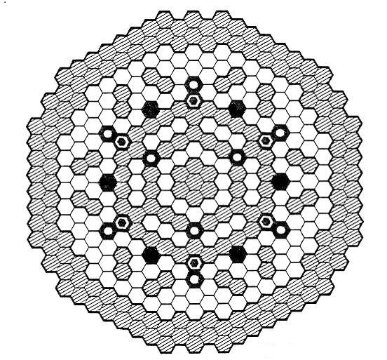
Figure 45 CRBRP heterogeneous core design
When describing LMFBR core designs, it is conventional to refer to the center assembly as occupying “row 1”, the six adjacent assemblies as occupying “row 2” and so on. Note that the seven center assemblies are all blanket assemblies. Row 3 consists of fuel assemblies; row 4 has 15 blanket assemblies and three primary control assemblies, and so on. The corners of row six are occupied by positions that are blanket assemblies for the first half of a two year cycle and fuel assemblies for the second half. Row seven has six primary and six secondary control assemblies along with 24 fuel assemblies. Note that in comparison with the homogeneous design, the heterogeneous design has just two rows of radial blanket assemblies and has twelve additional positions occupied by fuel, blanket, or control assemblies.
The heterogeneous core design proposed by the prime contractor had 156 fuel assemblies with about 30.5% fissile enrichment, 77 internal blanket assemblies and 132 radial blanket assemblies. The six positions that were intended to be loaded with internal blanket assemblies for one year then changed out for fuel assemblies were provided to recover reactivity lost during the first year of operation.16 12 of the 324 removable shield assemblies in the homogeneous core design were replaced with radial blanket assemblies. Some of the shield assemblies were changed to Inconel to improve their shielding effectiveness. At the end of two years, the entire central core region would be replaced including all the internal blanket assemblies. There were two rows of radial blanket assemblies and the inner row blanket would be renewed after four years of operation while the outer row would be renewed after five years.
CRBRP was led to the heterogeneous design primarily because of the artifact that required it to use the same pin diameter as the FFTF. This was mainly motivated by the large fuels data base that was expected to be collected by FFTF operation and the need to make use of that data base on CRBRP. Another incentive may have been the concern that if CRBRP were to use a different fuel from FFTF, it would remove one of the incentives for completing the FFTF project. After the design team had made their proposal and it had largely been acceptable to the Project Office, representatives from Argonne National Laboratory pointed out that the same breeding ratio could have been achieved in a conventional two region core by using fuel with a pin diameter of 0.24 in. rather than the 0.23 in. used in CRBRP. The pressure drop across the pin bundle would have been greater but it probably could have been accommodated by the oversized primary system pumps. If the constraint of using the FFTF fuel design had not been applied to the CRBRP project, it is doubtful the heterogeneous core design would ever have been developed.
It turns out that heterogeneous designs have another important hidden advantage. Much of the plutonium production occurs in a region of high neutron importance (the word “importance” as used in this context should be assumed to have the meaning associated with its use in perturbation theory) which opens the door to very long lived cores. With homogeneous designs, the neutron flux gradually moves outward toward the radial blanket as increasing amounts of fissionable material are produced there. Plutonium has a lower importance in the outer reaches of the core than it does in the center, and the core gradually loses reactivity. Heterogeneous cores can be designed so that the plutonium production is greater near the center of the core where it has the greatest importance to reactivity. This is of key significance for designing a reactor where the reactivity swing is to be minimized so that it can operate for long periods between refueling.
A secondary effect that also contributes to the designer’s ability to provide for long core lifetime is the shielding afforded by the blanket pins closest to the fuel assemblies. The power level and plutonium production provided by the interior blanket pins increases as the fissionable content in the outer layers of pins increases. It is this line of thinking that suggests that thickening the layers of the parfait, particularly the blanket layers, may contribute to the long life objective.
It is instructive to consider the dimensions of a large heterogeneous core with parameters set to the assumptions of this paper. A 271 pin bundle will be assumed for the fuel assemblies. This is one row of pins greater than CRBRP and equal to the number of pins per fuel assembly used on Superphénix. There is nothing particularly magic about a 271 pin fuel assembly bundle. The larger the number of pins per bundle, the lower the fuel fabrication cost, the better the breeding ratio, and to a small extent, the lower the pressure drop across the assembly. It is difficult to argue that a 331 pin bundle wouldn’t be preferable to a 271 pin bundle. A larger fuel assembly would reduce the flexibility in the core design but this is probably not a strong argument. Other considerations do come into play such as refueling and shipping, both of which are more challenged by a larger fuel assembly. The 271 pin bundle is selected primarily on the basis of Superphénix precedent and the objective of avoidance of unnecessary surprises more than any other reason. A 271 pin fuel bundle with 0.33 in. pins, a slightly higher wire diameter, and duct thickness about the same as CRBRP would measure 7.19 in. across the flats. The wire diameter was increased from a CRBRP value of 0.056 to 0.060 so as to improve flow area. There will be more on this subject in the thermal dynamics section.
The number of pins per blanket assembly is another matter. If it is planned to leave the blanket assemblies in place for ten years, the pins must be small enough so their pin power limits would not be exceeded at the end of the cycle. The only way to make this determination with certainty would be with analysis of the selected core design, but a reasonable estimate can be made by extrapolation from CRBRP analyses. For CRBRP, the inner blankets produced about 7% of full reactor power at the beginning of an equilibrium cycle and about 16% power at the end of an equilibrium cycle. At this point, many of the CRBRP blanket pins were approaching limiting pin power. The CRBRP blanket pins each contained 6.1 times the volume of the respective fuel pins. Given the greater fuel pin diameter in the proposed design (there is 2.3 times the heavy metal per inch in 0.33 in. diameter pins vs. 0.23 in. diameter pins), 2 years of residence in the CRBRP core is about equivalent to 3.6 years in the proposed core allowing for the different assumed capacity factor. Therefore, 10 years in the proposed core is about equivalent to 5.5 years for the CRBRP or 2.7 cycles. If the proposed blanket pins are no more than 6.1/2.7 = 2.26 times greater in volume than the fuel pins, the system should work. It turns out that this corresponds to a blanket pin diameter of about 0.47 in. with the same pin wall thickness of 0.015 in. For the duct size selected, this corresponds to a 127 pin bundle.
Blanket assemblies with 127 pins per bundle for the duct size selected would have a pin diameter of 0.47 in. The inner blanket assemblies would be producing about 25% of total core power at the end of the 10 year cycle.17 If one scales up to 3000 MWth from CRBRP accounting for the difference in the number of pins per fuel assembly, there would be approximately 375 fuel assemblies, 228 internal blanket assemblies, and 396 radial blanket assemblies. The number of control assemblies would increase, but not necessarily in proportion to size. For the purposes of this discussion, it is assumed there would be 30 control assemblies. Fortuitously, there was a heterogeneous oxide core design study performed by ANL at the 3500 MWth size and is shown below.

Figure 46 ANL 3500 MWth core design study
The ANL study18 appears to have been conducted primarily to explore the advantages of metal fuels, but it nonetheless provides some information that is useful. It had smaller diameter fuel pins (0.285 in.) and thicker clad (0.022 in.) than is assumed herein. There are 396 fuel assemblies, 163 internal blanket assemblies, and 90 radial blanket assemblies. The active core region was 40 in high. This core was designed for annual refueling of 1/3 of the core. Note that there is just one row of radial blanket assemblies and three rows of shield assemblies. The ANL study enabled reduction of the number of shield assemblies by retaining just one row of metal shield assemblies and replacing the outer rows with boron assemblies. The inner row of metal shield assemblies helps reflect some neutrons back into the core, while the boron assemblies make a better shield material for protection of the core barrel. The single row of radial blanket assemblies is an acknowledgement of the low value of the second row of radial blanket assemblies and the usefulness of making more room available for core assemblies. Note also that of the 36 control assemblies, 24 are surrounded on six sides by fuel assemblies. The remaining twelve have blanket assemblies on two sides only. This action was taken to improve the worth of the control assemblies. All of these ideas have merit.
The ANL core design could be expanded by two additional rows and still result in a core diameter of less than 21 feet using the pin diameter and duct size assumed in this paper. Adding some room for fixed radial shielding would bring the core barrel diameter to less than 23 feet. Assuming the space between the core barrel and the reactor vessel is minimized, a topic treated in the refueling section of this paper, there should result a reactor vessel diameter no greater than 28 ft. This 28 ft. diameter reactor vessel is the target diameter for the purposes of this paper. It is possible it could be reduced further pending detailed core design calculations. 28 feet probably represents a reasonably good upper bound.
One final topic that requires treatment is the height of the active core region. On CRBRP and FFTF, the active core was 36 in high which is a fairly typical number. Core designs tend to be short in LMFBRs since the sodium coolant is effective at removing heat. Three feet of active core height are usually all that is required to raise coolant temperature the required amount while remaining within linear power limits and additional length would add to the fissile inventory and was seen to serve little purpose. It is noteworthy that the Superphénix plant had an active core height of 1000 mm (39.37 in) and the planned Superphénix II was being designed for an active core of 1200 mm (47.24 in). It appears that the French saw an advantage to lengthening the active region of the core. There are two good reasons for doing so. First, a longer core leads to lower power density per foot of pin length and/or permits a higher ΔT across the reactor. The lower power density per foot allows for higher hot channel factors, should they develop in the design. Second and of greater importance, a greater core height increases the total heavy metal inventory in the core and allows for more total energy production per refueling cycle within limits of allowable burnup.
If one uses the assumed plant capacity factor (defined later in this section), assumes a ten year interval between refuelings, assumes 65% of the energy developed by the reactor comes from the fuel assemblies in the active core region, assumes an average of active fuel assembly 15 a/o burnup would be consistent with a peak burnup of 30 a/o, uses the number of fuel assemblies in the proposed design (identified later in this section) and uses the thumb rule that 1 gram uranium = 0.95 MWth-day, it is straightforward to calculate (0.65% X 365days per year X 3000 MWth X 10 years X 0.95 MWth per gram HM ÷ 0.15 a/o X 0.95) that 47.480 MTU must be in the active core region of the fuel assemblies. For this to work consistent with the parameters selected for the fuel assemblies, the active core region must be at least 47 in high. Rounding to the nearest whole foot, a 48 in high active core region will be used. Adding a foot to the active core region has the added advantage of holding down the linear pin power of the inner blanket assemblies, which could prove to be problematic toward the end of the cycle after substantial plutonium has bred into them. An alternative would be to add fuel assemblies, but doing so would add to the reactor vessel diameter and would probably be much more expensive than simply lengthening the fuel assemblies when the only purpose is to increase the heavy metal inventory.
The core design that is being proposed here is not radical. By way of comparison, the Superphénix reactor, which also had a nominal 1200 MWe output, had 0.33 in. diameter pins with 271 pins per bundle. There were a total of 364 fuel assemblies, 233 blanket assemblies (in 91 pin bundles) and 21 control assemblies. It was planned to replace 1/5 of the core each year for a 5-year residence time of the average fuel assembly. Even with a 5 year residence time, burnup was intended to be limited to 9 a/o. Superphénix clad thickness at 0.022 in. is slightly thicker than the 0.015 in. proposed here. The core proposed here would run at a slightly lower pin power than Superphénix and rather than annual refueling, the whole core would be refueled on ten year intervals. The big changes from Superphénix are the heterogeneous core design, vented fuel, and controllable flow to the blanket assemblies as will be discussed in the thermal-hydraulics subsection which follows. It should be noted that once thermal-hydraulic analysis of this proposed core approach is undertaken, it is expected that it will prove unnecessary to provide variable flow to the fuel assemblies however the internal blanket assemblies would most likely require it.
The tricky part of making this long lived core work will be to achieve the desired reactivity swing with burnup. It would be desirable for the reactivity to slowly increase for the first five to six years of operation and decrease for the last four to five years. The control rods would be almost fully withdrawn at both the beginning and the end of the ten year cycle and inserted to their maximum allowable at some point near the middle of the cycle (except for the secondary rods, which would be always fully withdrawn when the reactor is operating). Although the CRBRP project may have been the first to incorporate a heterogeneous core design as the reference design for a plant that was intended to be built, that project did not invent the concept. Prior to the mid 1970s, heterogeneous core designs were referred to as “parfait cores”.19 The trick to controlling the reactivity swing of these “parfait cores” may be to thicken the layers of the parfait. Adopting a core that is larger than necessary to remain within peak linear power limits may well be what is needed to thicken the layers and achieve the cycle length objective.
Another degree of flexibility that could be called upon would be to extend the fuel assemblies by a foot or so and insert a layer of blanket material between two 24 in. fueled zones. This is the so-called “axial parfait core”. In addition to its potential for improving breeding, such an approach would also tend to reduce the hot channel temperature by providing a greater degree of intra-assembly mixing. Doing this would add to the length of the reactor vessel and would introduce irregular reactivity behavior from the control rods over their travel through the inner blanket. It could theoretically lead to oscillations between the upper and lower core zones if the nuclear coupling between them is weak; however, there is no obvious mechanism (such as Xenon poisoning in a LWR) that would initiate such oscillations. This axial parfait approach might be worthy of consideration if the proposed core proves incapable of meeting the operational goal of a ten year refueling interval. A core design that incorporates all the features being advocated (except for the horizontal inner blanket layer) is shown in the figure below.
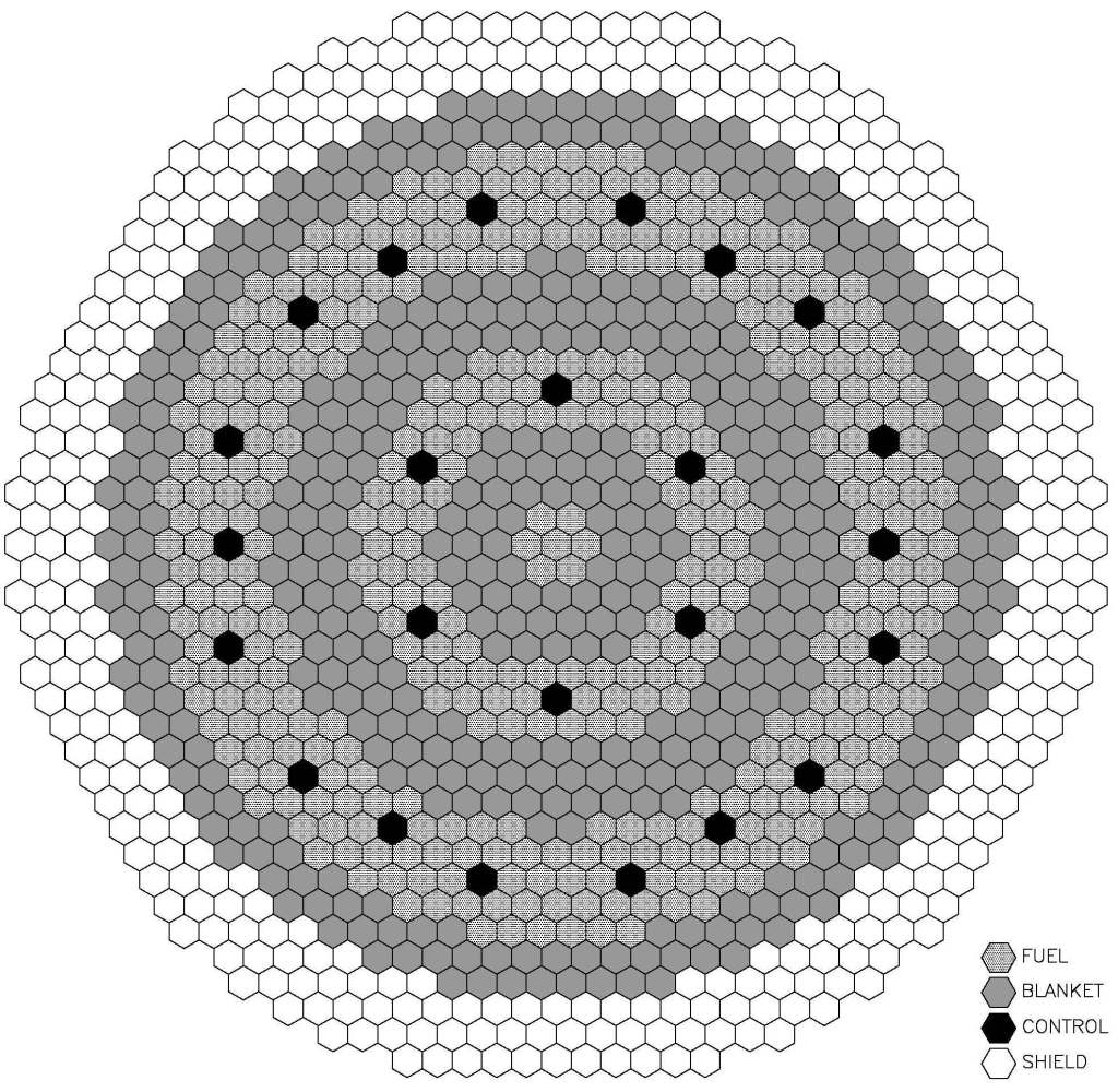
Figure 47 Proposed core design
There are 397 fuel assemblies, 228 internal blanket assemblies, 198 radial blanket assemblies, 24 control assemblies, and 342 shield assemblies. This is comparable to the scale-up of the CRBRP core but with 22 more fuel assemblies and 198 fewer radial blanket assemblies. Fewer radial blanket assemblies make sense from two points of view. First, the CRBRP core design had two rows of outer radial blanket assemblies as does this design. Second, the inner row of CRBRP radial blanket was intended to run for two equilibrium cycles and the outer row for 2 ½ equilibrium cycles. The proposed radial blanket is intended to run for just one equilibrium cycle. It is reasonable therefore to expect that the proposed design would have a relatively thinner radial blanket. The assembly count comparison between the CRBRP scale-up, Superphénix, the ANL core and the one proposed in this paper is shown in the table below.
| CRBRP scale-up | Superphénix | ANL (3500 MWth) | Proposed design | |
| Power level, MWth | 3000 | 3000 | 3500 | 3000 |
| Fuel assemblies | 375 | 364 | 396 | 397 |
| Inner blanket assemblies | 228 | 0 | 163 | 228 |
| Outer blanket assemblies | 396 | 233 | 90 | 198 |
| Control assemblies | 30 | 21 | 30 | 24 |
| Height of core, in. | 36 | 39.37 | 40 | 48 |
| Fuel pin diam., in. | 0.23 | 0.33 | 0.285 | 0.33 |
| Clad thickness, in. | 0.15 | 0.22 | 0.22 | 0.15 |
| Fuel pins per bundle | 217 | 271 | 271 | 271 |
| Blanket pins per bundle | 61 | 91 | 127 | |
| Blanket pin diam., in. | 0.51 | 0.55 | 0.47 | |
| Refueling interval | Biannual w/ mid cycle adj. | 1/5 of core, annually | 1/3 of core annually | Once every 10 years |
Table 8 Core assembly comparison of various designs
In the proposed design, all of the control assemblies are surrounded on six sides by fuel assemblies, so as to enhance their worth. Since it is planned to run the core for ten years between refuelings, the radial blanket is two layers thick in contrast to the ANL approach of having a single layer of radial blanket. The neutron flux profile will probably tend to move outward as a result of the thicker blanket however some counteracting inward motion of the profile would also be expected because of the heavy concentration of blanket assemblies toward the middle of the core. As shown, this core is about 18.5 feet in diameter – an additional three rows of shield assemblies would bring the diameter to just above 22 feet, somewhat above the 21 ft. goal. The inner blanket layers are purposefully thick in the interest of reducing reactivity swing with burnup, particularly early in the life of the core. There are somewhat more inner blanket assemblies than the ANL design (which had 16% greater thermal power) and almost the same number of fuel and radial blanket assemblies. There are six fewer control assemblies which could readily be added to the outer fuel annulus at the expense of either six inner blanket assemblies or six fuel assemblies. As many as 18 fuel assemblies can be traded for inner blanket assemblies and still remain within the CRBRP scale up parameters if it proves necessary to do so in order to prevent exceeding inner blanket pin power limits.
There is little doubt that if analysis were to be pursued on this core design, it would change. As was stated earlier, four years of design activity occurred on the CRBRP heterogeneous core before the design was settled. Had the project not been terminated, it is likely that further changes would have been made. The purpose of advancing the design shown is to suggest a starting point and to propose some ideas that may have merit towards the objective of developing a core design that can be operated for ten years between refueling outages.
It is necessary to identify the core assembly length for the following subsection as well as determining its impact on the reactor vessel, the EVST, the refueling cell and the other components of the refueling system. The CRBRP core assemblies were designed to be 14 ft. in length, which included 3 ft. for inlet and outlet hardware. (The split between 8″ for the upper axial blanket and 14″ for the lower axial blanket is almost certain to change. BN-600 has lower and upper axial blanket thicknesses of 13.8″ and 11.8″ respectively, which appears to be a result of optimization. Earlier designs had different splits. The choice must await analyses.) The inlet and outlet hardware will be treated in the following paragraph. As for the remaining 11 ft, 4 ft. of fission gas plenum has been removed, 12″ of fueled region has been added, and 6″ of upper axial blanket has been removed. With the fission gas plenum removed, it will probably be necessary to provide some shielding above the upper axial blanket to protect the UIS from excessive fluence. Without performing analyses, it is not possible to determine how much shielding will be required, so a placeholder of 12″ will be assumed. This 12″ figure probably isn’t too far off the mark since the lower shield is 20″ in length – a value which has been retained – and the effectiveness of any upper shielding would get an assist from the control assemblies. This leaves the core assembly length at 9 ½ ft. plus inlet and outlet hardware.
The outlet hardware consists of a load pad for the core restraint system and a fixture for a grapple. This occupies about 8 in. and there is little opportunity for improvements. The inlet hardware, however, appears to offer opportunities for shortening. There is a discrimination fixture at the bottom of the assembly and windows for admitting coolant. Other than that, it is little more than a 2 ½ ft. hollow tube. The assembly orificing is accomplished in the shield block above the inlet nozzle. There does not appear to be anything in the PSAR or the available open literature that accounts for this long inlet nozzle. It should be reduced by at least one foot, which would leave the overall assembly length at 11 ½ ft. It is likely that another half foot could be removed from this inlet nozzle without compromising function.
There is a piece of information that is missing that is required by the core designer, viz. what capacity factor should be assumed. When CRBRP was designed, nuclear plants in the US were lucky if they were able to achieve a 75% capacity factor. It is possible that there was no conscious decision that led to the 75% assumption for the CRBRP design, and that is what was typically used by NSSS vendors.20 However, things have changed since then. Nuclear plants in the US routinely achieve 90% capacity factors year after year including provisions for their refueling outages. This is a reflection of their value as base loaded plants with high capital costs and low fuel cycle costs as well as intelligent capitalization on experience by their utility industry owners. The same capital argument applies to LMFBRs, and little good would be served by advertising them as being designed for a lower capacity factor than that which has been routinely achieved by LWRs. They must be designed assuming they will be run at nearly full power between refuelings even though, because of load following, this may turn out not to be the case. Since the refueling is expected to require up to six months, the plant should be designed for 95% capacity factor between refuelings. This would work out to be slightly better than 90% overall capacity factor assuming six month shutdowns for refueling.
The table below compares the heavy metal loading of the fuel, axial blankets, inner blanket and radial blanket between CRBRP and the selected concept.
| CRBRP | Proposed design | Proposed design, modified definitions | |
| Fuel | 5.189 | 50.570 | 50.570 |
| Upper axial blanket | 2.112 | 8.820 | 14.030 |
| Lower axial blanket | 2.112 | 15.440 | 24.560 |
| Inner blanket | 8.270 | 45.600 | 31.270 |
| Radial blanket | 12.707 | 39.600 | 39.600 |
| Total | 30.390 | 160.030 | 160.030 |
Table 9 Heavy metal loadings, CRBRP vs. proposed design (MTU)
The CRBRP figures as well as the first column for the proposed design include the upper and lower axial blanket extensions of the inner blanket into the inner blanket numbers. If those extensions are incorporated into the numbers for the axial blankets for the proposed design, the result is the final column, which gives a better picture of the actual heavy metal content of the axial blankets. The radial blanket includes the extensions in all cases. The proposed design has just over five times the heavy metal loading of CRBRP with proportionately less in the radial blanket and upper axial blanket and proportionately more in the fuel.
It also should be noted that the JSFR-1500 design, which is dealt with in this paper when treating the heat transport system, has a proposed fuel pin diameter of 0.43 in. Achievement of the 10 year cycle could alternatively be accomplished with larger fuel and internal blanket pin diameters. Possibly, some reduction of the number of core assemblies could be effected. A larger pin diameter would be likely to lead to a larger core diameter and a larger reactor vessel diameter.
D Thermal-hydraulic design
The main problem with heterogeneous designs has already been alluded to – viz. large swings in power generated by the inner blanket assemblies during operation. The CRBRP blanket assemblies had just 61 pins per bundle. At beginning of cycle 3 the fuel assemblies were predicted to produce 84.24% of full core power while the inner blankets produced 7.72%, entirely from fission of U238. At the end of cycle four, the split was predicted to be 72.02% for the fuel and 17.2% for the inner blankets. Once the plutonium builds up in these pins to the neighborhood of 6%, their individual pin power was predicted to become somewhat greater than that of the fuel assemblies, and it would become necessary to remove them from the core to prevent them from overheating.21 One could ameliorate this problem by using blanket assemblies with 91, 127, or even 169 pins at a small penalty to breeding ratio and a somewhat greater cost for blanket assembly fabrication which would delay the onset of the problem.
But then another problem emerges. Both the fuel and the blanket assemblies are orificed so as to optimize coolant use by the entire core. On CRBRP, the flow had to be optimized for the inner blanket assemblies assuming the plutonium concentration that would exist after they had resided in the core for two years. The blanket assemblies were overcooled at the beginning of their cycle and a little bit under-cooled at the end of the cycle. If one’s objective were to design a core capable of operating for ten years between refueling, optimum flow for an internal blanket assembly at beginning of life would be woefully inadequate for the same assembly after it had resided in the high flux region of the core for ten years and had built up a substantial plutonium concentration. Failure to achieve optimal flow in all the core assemblies means that more flow must be provided to assure adequate flow in the assemblies that are producing the most heat. Optimum flow for the blankets at the end of cycle would be excessive at the beginning of the cycle and would lead to excessive thermal striping of the upper internals structure. Non-optimum flow also means that more flow must be supplied to the core increasing pressure drop. For the case of CRBRP, the flow split to the fuel, inner blanket and radial blanket assemblies was set at 65%, 17%, and 12% respectively. This makes reasonable sense when the power split is 72%, 17% and 11% respectively at the end of an equilibrium cycle. But at the beginning of the cycle, the power split is 84%, 7% and 9%. It is easy to see that for this case, the inner blankets were overcooled by about 140% at the beginning of the cycle.
Overcooling the inner blankets means the fuel assemblies must run hotter. Using the flow and power splits above and assuming a 265°F mixed mean temperature rise across the reactor, if the assemblies receiving 65% of the flow are generating 84% of the power, the average temperature rise across these assemblies must be 342°F while the temperature rise across the inner blankets that are receiving 17% of the flow but generating just 7% of the power is 109°F. For the case of CRBRP, 6% of the flow was provided for control & shield assemblies, reactor vessel cooling and leakage. If the power to flow ratio of the remaining 94% could be maintained equal, 22 the temperature rise would be 282°F, 70°F lower than the 342°F cited earlier. Achieving greater balance in the temperatures between the fuel and the inner blanket assemblies could provide a pathway for increasing the mixed mean reactor outlet temperature by 50°F or more. A 50°F increase in reactor mixed mean outlet temperature translates into a thermodynamic efficiency improvement of about 3%, which would improve the plant’s electric power output by about 10%.
In the paragraph before last, the subject of thermal striping was brought up. This would be a good time to describe it, since it seems to be a problem unique with liquid metal cooled reactors, and it is aggravated by heterogeneous cores. When the sodium exits the core assemblies, it is mixed in the upper internals structure. There is a period before complete mixing occurs when the regions of the upper internals structure that are closest to the core are exposed to widely varying temperatures attendant with turbulent flow and the mixing from the coolest and the hottest assemblies. These temperature swings can occur with a short period – on the order of a second. Temperature variations of 200°F or more produce internal stress in the structures and expose them to fatigue and potentially, ultimate failure.
Heterogeneous core designs have the obvious appeal of effectively capitalizing on the most important attribute of the LMFBR – its breeding capability – inside the high flux region of the core itself, by making relatively inexpensive blanket assemblies contribute in a meaningful way to the job of producing power along with the much more expensive plutonium-bearing fuel assemblies. Except for the change-out of the six assemblies after odd years of operation, the CRBRP core came reasonably close to the objective being advocated, i.e. whole core refueling on infrequent intervals. With a higher fuel pin diameter and a greater number of blanket pins per bundle, the heterogeneous core design offers a promising possible approach to achieving the ten years between refueling that is advocated, except for the thermal-hydraulic problem caused by the heat production growth in the internal blankets.
There is an obvious solution that both optimizes flow and prevents thermal striping. The fixed orificing could be abandoned in favor of variable flow control devices at the inlet (or outlet) of each core assembly that is controlled by the assembly outlet temperature. It may turn out to be possible to remove the orifices from many of the fuel assemblies while providing less restrictive orifices for the remainder, orifice the shield and control assemblies, and provide variable flow only to the blanket assemblies. As more flow is directed to the inner blanket assemblies, the flow to the fuel assemblies (which would be producing less power) would decline while total core flow remains approximately constant.
Variable flow control to core assemblies was actually provided on the Hallam reactor plant by mechanically varying the core assembly orifices remotely through a flexible drive shaft.23 This Hallam feature had problems with galling and binding of the control cable which may have discouraged further development of the concept. Nonetheless, the company that designed the Hallam reactor (North American Aviation) participated in the CRBRP project as Rockwell International. After it became clear that the heterogeneous design would probably be adopted on the CRBRP project, Rockwell was assigned to perform a study of variable flow control concepts which addressed and resolved the problems that occurred at Hallam and offered a totally diverse design approach.24 One of the proposed concepts, similar to the Hallam approach is shown in the figure below.

Figure 48 Variable orifice concept
In this concept, a valve actuation rod under compression is inserted down through the center of the blanket assembly to a piston located in the inlet orifice region. In the concept shown, there are three possible positions for the piston. As the piston is moved from its uppermost location downwards, an increasing number of flow holes are exposed increasing flow through the assembly. The valve actuation rod is operated by an extendable portion on the grapple assembly at the end of the in-vessel transfer machine (IVTM). The alternative design proposed in the above cited reference involved rotating each of the inner blanket assemblies to expose greater flow area in the orifice region, which would be provided for by design of the core support structure region. These two manual concepts were developed for the CRBRP project and are not consistent with the overall design approach being advocated. A remotely actuated device would be preferable.
The above reference did not propose any automated flow control devices other than to identify four possible approaches for doing so:
- A bimetallic device
- Devices relying on differential expansion between an assembly bundle element and the assembly duct
- Devices relying on the thermal expansion of a fluid
- A device using an externally monitored temperature signal to drive an external system to adjust an assembly variable orifice (manual adjustment of the orifice position during operation is also a possible variation on this concept).
Of the above four ideas, no mechanistic implementation was proposed. The fourth (without the manual adjustment) is the most straightforward and is proposed for the purposes of this design approach. Development of such a device is an excellent choice for further R&D that would not necessarily involve operation of expensive facilities and could be performed on a limited budget. The following discussion is mainly offered as guidance.
Considerable simplification of the variable flow concept could be achieved by controlling the flow at the top of the assembly rather than the bottom. This approach was avoided in the aforementioned reference to avoid pressurizing the assembly duct and to allow for debris sweep-out during accident conditions. It is an approach that would be worthy of reconsideration if the core pressure drop could be significantly reduced lowering the pressure on the assembly ducts and if consideration of accidents requiring fuel sweep-out for mitigation were eliminated.
As for the means for actuation of the variable flow control devices, electromagnetic pumps have been developed that are capable of operating in this environment for up to 100 years.25 Assuming the control valve is electrically actuated, the EM pump development cited above provides a straightforward pathway to development of valve actuation motors. For orifices located at the bottom of the core assemblies, the power supply for these devices and their control would require some conduit probably through the fixed shield. (There is already instrumentation at the bottom of the upper internals structure for core assembly temperature measurement.) Locating the flow control at the top of the assemblies would greatly simplify this approach eliminating the need for running a conduit through the fixed radial shield. It would also be much more accessible if access becomes necessary. As an aside, controlling core assembly flow would capitalize on the ducted fuel in a way that PWRs will never be able to duplicate with un-ducted fuel.
The development of a core assembly flow control device has not been actively pursued to date likely out of concern for possible malfunctions that could shut off flow to a core assembly. Interruption of flow to selected assemblies was the cause of the partial meltdowns at the SRE and Fermi-1 reactors. There is a natural aversion to taking steps in the design that raise the prospect of such an event. This concern would need to be dealt with before such a device could be deployed. If this problem cannot be solved, the only alternative may be to abandon the heterogeneous design however, even in conventional homogeneous designs the radial blanket assemblies closest to the core will eventually build up plutonium and generate substantial amounts of power. Removal of the radial blanket may be a solution provided the fuel pins are sufficiently large in diameter to supply the necessary breeding. Such a design would replace the radial blanket assemblies with additional removable shield assemblies. It should be recognized that even in such a core, the power generation by individual fuel assemblies will not be constant throughout life. The neutron flux will tend to move outward as burnup builds in central assemblies at a rate greater than the peripheral assemblies. Moreover, there is a question whether a homogeneous core, regardless of the fuel pin diameter, can be designed to operate to high burnup levels with whole core refueling intervals of ten years that is advocated herein.
In the interest of reducing pumping power, another objective of the core design should be to reduce the head loss across the reactor as much as possible and significantly less than 50 psig. The larger fuel pin diameters, shorter fuel assemblies, and the elimination of inlet modules (see section 5) will help as will the removal of the orifices from the highest flow fuel assemblies and the provision for individual control of blanket assembly flow. As mentioned above, a larger fueled region of the core also helps. 50 psig should be easily within reach and even lower pressure drops on the order of 20 psig should be achievable. A reduced pressure drop across the core offers the potential to eliminate core assembly hydraulic hold down.
On the subject of hydraulic hold down, it is instructive to examine the details of the pressure drops across plant and core components on the CRBRP. CRBRP was designed for a fuel assembly pressure drop of about 110 psig. The assemblies with the highest flow had a 40 psig pressure drop across the assembly inlet orifices. It is not known how to justify this feature in the CRBRP design. Perhaps at some point, there had been some thought to increasing the fuel assembly pin diameter, (which would have reduced the pin bundle flow area increasing core pressure drop) but if so it was not advertised by the contractor. More likely, the primary pump capability had been selected before the core requirements had been determined. Eliminating those orifices on the highest flow assemblies would immediately reduce the pressure drop across the core to 70 psig. Eliminating the four foot plenum gas space and reducing the thickness of the axial blankets would probably yield another 10-15 psig. The more open lattice of the fuel design being proposed would be good for further reductions.26
The CRBRP designers did not have much of an incentive for streamlining the core assembly hardware since the primary pump head had been established early in the project and its head was more than sufficient. In fact, it was more than was needed. The pressure drop across the fuel assembly orifice with the highest flow is ample testimony to that. On CRBRP assemblies, the inlet nozzle, shield, rod bundle inlet, rod bundle outlet, and outlet nozzle together represented 18.4 psig of head loss for the fuel assembly with the highest flow rate. If there had been an incentive to reduce this number, it could undoubtedly have been be lower.
The figure below shows how hydraulic hold down of core assemblies was accomplished on the CRBRP design.
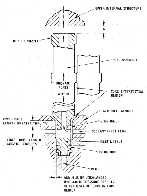
Figure 49 CRBRP hydraulic hold down feature
Coolant flow enters a region just above the fuel assembly inlet nozzle. The region below the inlet nozzle is vented to a low pressure region through ports in the core plate that lead to the interstices between the core assembly ducts. There will be some leakage flow past the piston ring in the fuel assembly inlet nozzle. This through core leakage flow joined with other leakages from the lower inlet modules amounted to about 1.05% of total core flow.27 This is flow that would otherwise be available for cooling the core. These relatively small leakage flows can turn out to be quite consequential. The entire plant is designed for thermal hydraulic conditions which include significant uncertainties. After the plant has operated and actual conditions are measured, the plant output can be increased to “stretch conditions” which remove many of the thermal hydraulic uncertainties. Any actual leakages are lost for good and cannot be recovered when moving to stretch conditions. 1.05% total leakage flow could correspond to an additional 12 MWe of generated electric power.
With pressure drop across the fuel assemblies controlled to be in the range of 20 psig, it should be possible to eliminate the hydraulic hold down feature from the fuel assemblies. The upward force from a 20 psig pressure differential across the fuel assemblies would be about 390 lb. The fuel assemblies with the dimensions that have been selected are expected to weigh about 1100 lb. Given approximately 100 lb. of buoyancy from the sodium, the weight of the assembly would be more than sufficient to overcome the hydraulic lifting force. Reducing the pressure drop across the core assemblies further would add margin. Elimination of this hydraulic hold down would be one more simplification to the core design and it should be pursued. It would be desirable if the core pressure drop could be reduced even further as was evident from the discussion of the heat transport system. There is precedent for a significantly lower pressure drop across the core than the CRBRP was designed for. The pressure drop across the Monju core was designed to be just 36 psig and the JSFR-1500 design core pressure drop is 43 psig.28
Reducing the core pressure drop also enables the realization of another advantage of sodium cooled reactors vs. water cooled reactors as discussed in Section 3. In water reactors, the control rod mechanisms are pressurized, necessitating treatment of control rod ejection accidents. On CRBRP, control rod ejection accidents required treatment due to the potentially high hydraulic lifting force on the control assemblies should hydraulic holddown fail. With the lifting force reduced significantly below the weight of the control assemblies, there is no credible mechanism for control rod ejection accidents, and they can be eliminated from the design basis. This is identified as CRM 53 in Appendix 10.
A lower pressure drop across the core should not result in any flow maldistribution problems. The CRBRP PSAR states (section 4.4.2.6), “At the10% pony motor flow level after shutdown; insignificant flow redistribution occurs between the parallel flow core assemblies. However, for the core natural convection cooling mode, the effect of dynamically approaching low flow with worst case decay heat loads results in a-power-to-flow ratio greater than one. Consequently, core temperatures increase and natural convection phenomena such as inter- and intra-assembly flow redistribution due to different thermal heads and hydraulic characteristics of the core assemblies become important. In general, the core thermal head becomes significant relative to the form and friction loss across the core below 5% full flow.” The message here is reasonably clear. As the primary system flow is decreased and natural circulation becomes more important, the flow distribution actually improves. There does not appear to be any incentive to design the core for any more pressure drop than is absolutely necessary to remove the heat produced by the fuel and blanket assemblies and the lower the pressure drop, the better. In fact, in the extreme, the prospect of designing the reactor for natural circulation at power is worthy of consideration and is treated in the next subsection.
The following summarizes the steps that have been (or will be) proposed for reducing the core pressure drop in comparison to CRBRP values:
- Eliminating the orifices on the highest flow fuel assemblies reduces core pressure drop from 110 psi to 70 psi.
- Increasing the number of fuel assemblies beyond that required for scale up to the higher thermal power of the proposed design: 5.6% reduction in average fuel assembly flow translates into an 11% reduction in assembly pressure drop.29
- Increasing reactor ΔT (see section 16 under parameters selection): 39% improvement. Items 1, 2, and 3 alone would reduce the pressure drop across the fuel assemblies to 38 psi. Assuming the split between the pressure drop across the pin lattice and assembly hardware remains the same as CRBRP (2/7 across the hardware and 5/7 across the pin lattice) this 38 psi would be divided into 11 psi across the hardware and 27 psi across the pin lattice. The following items would reduce the pressure drop across the pin lattice:
- Increasing relative flow area in the pin lattice (flow area divided by number of pins) from 0.0334 in2 to 0.0619 in2: 46% velocity reduction and 71% pressure drop reduction.
- Reducing the pin length from 114.4 in. to 72.4 in.: 37% reduction.
- Greater wetted perimeter of the proposed design per pin: 40% increase.
Items 1, 2, and 3 alone would reduce the pressure drop across the fuel assemblies to 38 psi. Assuming the split between the pressure drop across the pin lattice and assembly hardware remains the same as CRBRP (2/7 across the hardware and 5/7 across the pin lattice) this 38 psi would be divided into 11 psi across the hardware and 27 psi across the pin lattice. The following items would reduce the pressure drop across the pin lattice:
Items 4, 5, and 6 would reduce the pressure drop across the pin lattice from 27 psi to about 8 psi. The result is a pressure drop of 19 psi across the core even without taking any credit for streamlining efforts on assembly hardware. It is apparent from this result that the objective of reducing core pressure drop may have been pressed too far. For example, if the CRBRP wire diameter were retained there would be a small penalty in pressure drop but the breeding would be better. Tradeoffs such as these are made as a part of the design process. The point to be made is there is ample opportunity to make significant reductions in the core pressure drop and there is a big payoff for doing so.
The table below compares the key CRBRP fuel assembly design features with those being proposed
| CRBRP | Proposed design | |
| Number of fuel assemblies | 156 | 397 |
| Pins per assembly | 217 | 271 |
| Total number of pins | 33,852 | 107,587 |
| Pin outside diameter (in.) | 0.23 | 0.33 |
| Wire wrap diameter (in.) | 0.056 | 0.060 |
| Pin spiral wire pitch (in.) | 11.9 | 17.1 |
| Pin triangular pitch (in.) | 0.2877 | 0.4017 |
| Clearance between pins at wires (in.) | 0.0017 | 0.0017 |
| Clad thickness (in.) | 0.015 | 0.015 |
| Pin length (in.) | 114.4 | 72.4 |
| Pellet column length (in.) | 64 | 70 |
| Fission gas plenum length (in.) | 48 | 0 |
| Lower axial blanket length (in.) | 14 | 14 |
| Upper axial blanket length (in.) | 14 | 8 |
| Active fueled core region length (in.) | 36 | 48 |
| Total fueled region (in.) | 64 | 70 |
| Core pellet diameter (in.) | 0.1935 | 0.2935 |
| Shield block total length (in.) | 20 | 20 |
| Load pad OD (in.) | 4.745 | 7.19 |
| Duct across flat ID (in.) | 4.335 | 6.79 |
| Load pad thickness (in.) | 0.205 | 0.2 |
Table 10 Key fuel assembly design features comparison
Before leaving the subject of thermal hydraulic design, it is the practice of the designer to incorporate margin in the design so as to account for uncertainties. Uncertainties can include instrumentation accuracy, manufacturing tolerances, analysis uncertainties and physical properties and correlation uncertainties. These uncertainties must be combined with attention to the degree of independence of each source of uncertainty from the others using some algebraic formulation. When combined, these uncertainties produce a deviation around the expected condition that can be represented as a distribution curve with some characteristic standard deviation, usually represented as σ. Design values are then obtained by applying some multiple of σ to the nominal conditions. The results are design margins.
These margins appear in all the analyses and generally are beneficial in ensuring that hard limits are not exceeded in the plant. However, they do penalize the plant when it comes to output. Again, using CRBRP as an example, the thermal hydraulic primary hot leg design temperature was set at 995°F. As this temperature was used to design components that would be exposed to hot leg temperatures, there is little doubt that the plant would operate reliably at that temperature. However, the expected temperature in the hot leg was much lower. Even after 30 years of operation with expected fouling of heat exchange components and expected tube plugging, the nominal hot leg temperature was expected to be 960°F, 35°F below thermal hydraulic design value (THDV) conditions.
If it were possible to run the hot leg temperature up to its THDV condition, one would expect to improve thermal efficiency by about 2% which would yield about 7% more generated electric power. However, that is generally not possible because the steam plant is also designed for THDV conditions including the temperature and pressure of the steam inlet to the turbines. The solution to this dilemma is to design the steam plant for nominal conditions at the steam generator steam outlet. It probably would be prudent to provide some margin for error but not to the extent used to arrive at THDV conditions, which are generally predicated on a 3σ level of uncertainty. A similar approach was taken on the CRBRP project. If economic performance in the plant is to be achieved, every opportunity, no matter how small, must be capitalized upon.
E Natural circulation reactors
Natural circulation LWRs are known to have been designed, built, and operated at power successfully as a part of the Naval Reactors program. It is clear from the preceding subsection that if it were possible to design a LMFBR for natural circulation at power, a large number of problems would be solved. It would not be necessary to orifice any of the core assemblies as each would regulate its own flow. There would be no need to provide variable flow control to any core assemblies or raise any of the issues associated therewith. The ducts could be removed from all core assemblies, reducing parasitic neutron absorption, further reducing core sodium head loss, and improving breeding. Core assembly hold-down would become a non-issue. The issues of the location of the primary system pump and its design would be eliminated since there would be no pump. Thermal striping in the upper internals structure would no longer be of any concern. The primary system would be simplified. The old bogeyman of the loss of flow ATWS would be eliminated once and for all.
Elimination of the core assembly ducts is particularly appealing. Part of the core design process for LMFBRs involves determination of the ΔT across the ducts since this ΔT is responsible for duct bowing. Duct bowing is dealt with in core design with the location of the load pads on the ducts and the core restraint system. It was this duct bowing, combined with the use of a metal form fuel that was directly responsible for the meltdown at EBR-I. Duct bowing also complicates refueling since it inevitably leads to creep opposing the ΔT-induced bowing. Adding to the complexity is radiation induced swelling of the ducts. Elimination of the ducts would also probably result in the elimination of the wire wrap in favor of grids as are used in PWRs. The grids would be designed both to create the spacing of the pins and provide for assembly to assembly contact. The load pads on the ducts would be eliminated in favor of more modest grid contact plates that would permit either greater heavy metal density in the core, lower core pressure drop, or some combination of the two. Another benefit of removal of the ducts would be to greatly reduce any issues associated with assembly blockage. If there had been no ducts on Fermi-1, it is doubtful there would have been any assembly overheating.
Evaluation of natural circulation capability is a fairly straightforward process. The density of sodium at the selected primary cold and hot leg parameters (see section 7) of 693°F and 1017°F is 54.10 and 51.33 lb/ft3 respectively. Assuming the thermal centers of the core and the IHXs are 30 ft. apart in elevation,30 the natural circulation driving head is about 0.58 psi. From the previous subsection, the core pressure drop at 100% flow is 19 psi and assuming the remainder of the primary system circuit pressure drop is about 11 psi yields a total primary system pressure drop at full forced circulation flow of 30 psi. Given that the pressure drop across any fluid system varies as the square of the flow31, the available natural circulation driving head would yield a flow of about 13.9% of full system flow with forced convection for these temperatures.
While this result provides confidence that natural circulation is more than adequate to remove decay heat, it is difficult to be optimistic in the face of this result if one is contemplating the use of natural circulation for heat removal at power. For the case of the naturally circulating Naval reactors, not much is available in the open literature since the designs are classified, but since all current U.S. Naval reactors are water cooled, it seems reasonable to assume that the naturally circulating Naval reactors are probably assisted by allowing some boiling to occur in the core which would substantially raise the driving head, an option not available in a sodium cooled reactor.
Perhaps the situation is not quite so grim. It is obvious that the greatest benefit can be achieved by increasing the ΔT across the reactor. If it were possible to double the ΔT across the reactor, the heat transferred out of the reactor for a given flow would be doubled and, to a first order of approximation, the thermal driving head would also be doubled. The first question needing an answer is how low can the cold leg temperature be decreased? The answer probably is associated with the minimum trapping temperature. Assuming that the trapping temperature cannot be reduced much below 250°F, the lower limit on the IHTS cold leg temperature is probably 350°F which would suggest that the lowest possible primary system cold leg temperature would be around 400°F. As far as the hot leg is concerned, it would probably be counterproductive to assume anything much above 1050°F because of materials issues that are raised at these high temperatures, so 1050°F will be assumed. These temperatures correspond to a 650°F ΔT, which is two times greater than the reference values assumed above. Taking into account the increased thermal driving head associated with this ΔT and using the same pressure drop figures assumed above, the maximum allowable power from this reactor would become 13.9% X 2.01.5 ≈ 40%. At this juncture, things begin to look interesting. With the elimination of the primary system pump, simplification of the PHTS design, and the elimination of core assembly ducts1, a reduction of system pressure drop by another 50% should clearly be achievable for another factor of 21/2 which brings the 40% figure up to 56%. With these assumptions, increasing the core size by about 75% should just about do the trick.
1For the design concept being considered, the across the flats dimension of the fuel assemblies at the load pad is 7.19 in and the across the flat dimension at the inner duct wall is 6.79 in. For this design, removal of the ducts would make 10.8% additional flow area available. This would probably be accomplished by adopting a somewhat larger wire increasing the pin to pin pitch slightly. Since pin bundle pressure drop is proportional to the product of the wetted perimeter and the flow velocity squared divided by the flow area and the flow velocity is inversely proportional to the flow area, pin bundle pressure drop is inversely proportional to the cube of flow area. In addition, removal of the ducts reduces the wetted perimeter by 14.2% which proportionately reduces pressure drop. The combination of these two effects would result in a 39% reduction of pin bundle pressure drop. A greater reduction would be expected from assembly hardware. On CRBRP, the high flow assemblies were calculated to experience 8.7 psi across the inlet nozzle, 6.4 psi across the shield, 1.1 psi across the rod bundle inlet, 0.6 psi across the rod bundle outlet, and 1.6 psi across the outlet nozzle. All of these pressure losses would be expected to either vanish or decrease significantly with ductless fuel. The resulting full flow pressure drop across the core with this ductless fuel would therefore wind up somewhere in the vicinity of 5 psi.
How would such a PHTS be configured and what would be the implications on the design of the balance of the heat transport system? The reactor vessel of course would necessarily be larger. The design approach assumes a core diameter of 22 ft. and a reactor vessel diameter of 28 ft. The core diameter would need to be increased by 1.781/2 or 33% to 29 ft. and the vessel diameter to about 36 ft. There would be just over 350 metric tonnes of heavy metal (MTHM) in the core. Because of the greater core size, refueling would be required less frequently – on the order of once every 18 years. Assuming the fuel is a ceramic with a sizable Doppler coefficient, reactor control would be accomplished by a combination of control rod motion and steam plant demand. There would probably be four elevated IHXs surrounding and in close proximity to the reactor vessel with primary system flow on the lower pressure drop shell side and intermediate flow on the tube side. Return primary flow from the IHXs might be directed back into the reactor vessel at an elevated location in order to cool the region between the core barrel and the vessel wall. An overflow vessel would be incorporated into the design with an EM pump returning overflow sodium to the reactor vessel. There would be a connection to a cold trapping system, probably as a part of the overflow system, with an EM pump returning sodium back to the primary system. (There would be no incentive for either of these auxiliary functions to be naturally circulating.) A primary reactor auxiliary cooling system would be incorporated (see section 8) with separate tube bundles built into the IHXs and probably NaK on the tube side. A cover gas system would be provided with its associated treatment system circulating cover gas from and to the reactor vessel. IHTS flow rate would be matched to primary system flow with forced convection variable speed pumps, probably electromagnetic. There would be a greater number of control rods because of the larger core, probably in proportion to the core size.
Design of the steam generating system with 350°F IHTS cold leg temperature is not straightforward. It would not be possible to design for 2400 psig steam conditions. To understand why consider the case where feed water inlet temperature is 300°F. Saturation temperature for 2400 psig steam is 663°F. Assume WNa X CPNa = WH2O X CPH20 where CP is the specific heat and W is the weight rate of flow in the steam generator of sodium and water respectively. Thus at the onset of boiling in the steam generator, the sodium side temperature would be 713°F. 55% of the intermediate sodium energy would be consumed in adding approximately 325 BTU/lb of energy to the water side. Since an additional 383 BTU/lb would be required to convert the water to steam, the conversion to 100% quality steam would be incomplete at the steam generator outlet. Neither lowering nor raising the feed water inlet temperature or increasing the steam generator heat transfer area can help this problem.
There are two possible solutions to this dilemma. One would be to accept a much lower steam pressure on the order of 350-400 psig with a significant amount of superheat. Associated with this idea would be about a 6% loss in thermodynamic efficiency between 400 psig and 2400 psig steam at 950°F which represents a loss in plant electric power output of about 180 MWe. Another more aggressive solution would be to have two separate steam plants. In this scheme, IHTS sodium would pass through two separate steam generators. The first would lower IHTS temperature from 1000°F to 675°F and the second would lower IHTS temperature to cold leg temperature, 350°F. The hot plant would operate at a steam pressure of 2400 psig while the cooler plant would operate at 300-350 psig. It would be possible to design such a plant with the same number (four) of steam generators if two IHTS loops were combined to flow through each of the hot steam generators and then through each of the cooler steam generators. This scheme would recover about half of the lost thermodynamic efficiency.
However, there is yet another problem. Primary system flow would not vary linearly with core power level but, to a first approximation, it would increase with the square root of the power level. If one takes the power to flow ratio to be unity at 100% power, at 50% power, the power to flow ratio would be about 0.7. At this lower power to flow ratio, the ΔT across the reactor would decrease from 650°F to 460°F. Perhaps some control of the primary system inlet temperature could be achieved by regulating IHTS flow and the steam plant(s) but at a minimum, steam conditions would certainly change. It is unlikely that such a plant would be useful in a load following mode. More likely it would ascend to full power very slowly and remain there.
Startup also presents some interesting phenomena. If one were to assume a shutdown reactor at 400°F cold leg temperature with the decay heat level is 0.5%, flow rate would be about 7% and the ΔT across the reactor would be about 50°F. Presumably removal of this decay heat would be accomplished by the decay heat removal system. Prior to reactor startup heat removal would be shifted to the steam plant and the decay heat removal system would be removed from service. Once the reactor is taken critical, power level would be increased raising the reactor ΔT. At 5% power reactor ΔT would be about 145°F and at 20% power, reactor ΔT would be about 290°F. If there were two separate steam plants, at this temperature the second steam plant would be started. It may be easier to control this reactor by maintaining the cold leg temperature constant although maintaining a constant hot leg temperature, though more difficult, is not impossible.
The above suggests that it should be feasible to design a reasonably practical naturally circulating LMFBR if one were motivated to do so for any of the reasons suggested above, but it would require a fair amount of thought. Extensive testing of natural circulating phenomena in the core and the remainder of the PHTS would inevitably be part of the price to be paid for any such endeavor. Ductless fuel, while being highly beneficial, would be a new participant in the technology that would require much study and irradiation testing. Would bowing still be an issue? How should core restraint be approached? Considerable design and testing would be needed to optimize a system that minimizes head loss. Design of a steam plant that could operate under significantly changing steam conditions could be a challenge. This idea appears to have sufficient merit to warrant further development, perhaps in a future paper or better with a carefully thought out test. For the current purposes and in consideration of the many potential difficulties associated with such a reactor including the almost total lack of experience with even related concepts, it is not considered necessary for consideration for an initial large-scale LMFBR design. However, the design approach being contemplated with its emphasis on reducing core pressure drop may very well provide a pathway to such a reactor.
F Core design summary
Given an objective of developing a core design approach that potentially could operate for ten years at a high capacity factor between refueling, the following summarizes the main points of this section.
- The boron in the control assemblies should be fully enriched. It is much cheaper to enrich boron than add control assemblies.
- The thickness of the upper axial blanket should be reduced by about six inches. This is in response to the presence of blanket assemblies in the active section of the core which increases the heavy metal fraction of the axial blankets and the presence of the control assemblies, which decrease the effectiveness of the upper axial blanket.
- The fuel assemblies have 271 pins per bundle with 0.33 in. diameter pins. The blanket assemblies are in 127 pin bundles.
- The heterogeneous core design is adopted in the interest of minimizing reactivity swing with burnup. For the same reason, the layers of the “parfait” probably need to be relatively thick.
- The active core region is four feet high.
- The radial blanket thickness should generally be limited to no more than two rows in the interest of fuel cycle economy and minimizing reactor vessel diameter.
- Use a high density material such as Inconel for the inner row of radial shield/reflector assemblies. Use boron assemblies for the outer two rows. These steps are to be taken in the interest of minimizing reactor vessel diameter.
- In view of actual experience with operating LWRs, a 90% capacity factor should be assumed for the life of the plant.
- Adopt remote flow control for the blanket assemblies. The flow control device for the blanket assemblies should be on the assembly outlet rather than the inlet in the interest of simplification and improved access.
- Significantly reduce core assembly pressure drop to no greater than 20 psig.
- Eliminate orifices for the highest flow fuel assemblies.
- Eliminate core assembly hydraulic hold down in the interest of reducing core assembly length, simplifying the design, and reducing leakage flow.
- Reduce bypass flow to the extent possible in the interest of improving flow to heat producing assemblies.
- Design the components of the steam plant for nominal conditions rather than THDV conditions.
G Head Port Layout
The Reactor Vessel Design described in Section 6 is one of the key cost reduction measures of the “design approach” and is enabled by a reactor core that requires refueling infrequently. Refueling that occurs only once in ten years permits longer refueling outages, which in turn allows for elimination of much of the head shielding and eliminates the need for in-vessel handling of core assemblies. The purpose of this subsection is to establish the feasibility of this refueling approach, which was adopted by SRE and Hallam but has not been attempted on an LMFBR core. For the case of SRE and Hallam, there were far fewer fuel assemblies and they were not adjacent (there were moderator cans surrounding each fuel assembly), which facilitated access by a single rotating plug. The greater number and adjacency of the fuel and blanket assemblies complicates the problem for an LMFBR.
To begin, the figure below is a section of the core and blanket for the “design approach”.
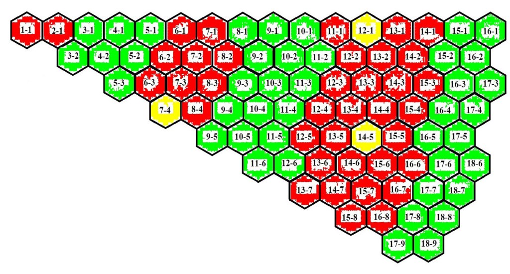
Figure 50 1/12 core section
Since the core has 12-fold symmetry, a 1/12 section totally describes the entire core. The fuel assemblies are shown in red, the radial blankets in green, and the control assemblies in yellow. It is a convention to number the core rows from the center outward, the middle assembly being the sole occupant of row 1, the adjacent six assemblies make up row 2, the next 12 assemblies compose row 3, and so on. Starting at the center, the across flats assemblies are position 1, their next neighbors are position 2, and so on as shown in the figure above. There are 83 unique positions, each having its own distance from the center of the core. The same section from the figure above is represented below with the distance from the center assembly shown below the assembly position number. The distances have been normalized to the assembly dimensions with the unitary being the across flats dimension, which for the “design approach” is 7.19 in.
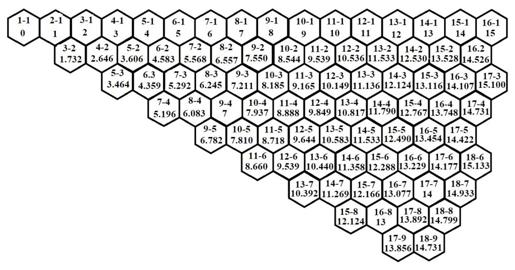
Figure 51 Normalized distances for assembly positions from the core center
The reason these distances from the center of the core is important results from there being a single rotating plug requiring multiple head ports to access the assemblies. It turns out that of the 83 unique positions, there are seven pairs that are equidistant from the center, 17-4 and 18-9 at 14.731 units, 15-1 and 17-7 at 14 units, 14-1 and 16-8 at 13 units, 14-3 and 15-8 at 12.124 units, 13-2 and 14-5 at 11.533 units, 11-2 and 12-6 at 9.539 units, and 8-1 and 9-4 at 7 units. Thus the 83 unique positions have 76 unique distances from the center of the core, requiring at most 76 head ports.
It is instructive to consider the situation at the center of the core where the layout of the head ports is the most challenging. The figure below shows the inner five rows of the core with 9 in. head ports superimposed on the drawing.
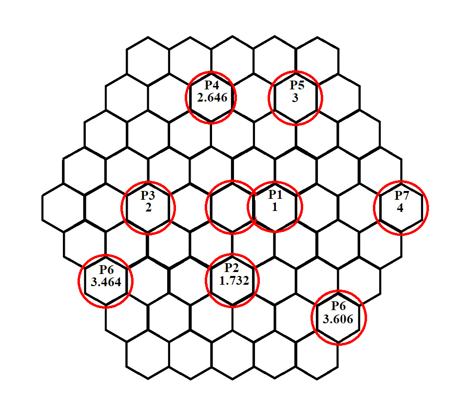
Figure 52 Inner Port Locations
The center port is the most challenging. The plug would be a figure 8 shaped with the circular portion over row two. When it comes time to access row one, the plug must be turned around. The plug handling machine must be capable of this maneuver. The closest that two plugs approach is between core positions 1-1 and 3-2. For 9 in. plugs, the web of metal between these two plugs is about 4.45 in. in minimum thickness. This contrasts with the space between plugs 1 and 3 of 5.38 in. The space between plugs 4 and 5 is the same. Note that there would be just one P6 plug — it is shown twice in the above drawing and its actual distance from the core center would be midway between the distances shown. It would probably be located near the lower right position in the figure above, and its diameter would be 11.5 in.
As one proceeds out from the center, more space becomes available for these plugs and one could readily arrive at a design for 75 port plugs (one less than the 76 mentioned above since plug 1 serves two locations. However, the distances from the center are close in many cases, which creates the option for larger diameter plugs covering a group of positions. The table below shows the results of the grouping that is possible when using 11.5 in. diameter plugs, which allow a diametric tolerance of 2 1/2 in. or 0.347 times across the flats. The equivalent figure is shown below the table. The “color code” refers to the figure. The positions in the figure that are not colored correspond to the positions for which there is a unique port. These unique ports would be 9 in. in diameter, while all others would be 11.5 in. in diameter. Plug 19 requires the greatest alignment tolerance et 0.3 times across the flats.
| Port No. | Lattice position & distance from center | Lattice position & distance from center | Lattice position & distance from center | Lattice position & distance from center | Lattice position & distance from center | Total assem-blies access-14-1, 13ed | Color code |
| 1 | 1-1 | 7 | gray | ||||
| 2 | 3-2, 1.732 | 12 | |||||
| 3 | 3-1, 2 | 6 | |||||
| 4 | 4-2, 2.646 | 6 | |||||
| 5 | 4-1, 3 | 6 | |||||
| 6 | 5-3, 3.464 | 5-2, 3.606 | 18 | light green | |||
| 7 | 5-1,4 | 6 | |||||
| 8 | 6-3, 4.359 | 6-2, 4.583 | 24 | yellow | |||
| 9 | 6-1, 5 | 7-4, 5.169 | 7-3, 5.292 | 24 | tur- quoise | ||
| 10 | 7-2, 5.568 | 12 | |||||
| 11 | 7-1,6 | 8-4, 6.083 | 8-3, 6.245 | 30 | blue | ||
| 12 | 8-2, 6.557 | 9-5, 6.782 | 18 | maroon | |||
| 13 | 8-1,7 | 9.4,7 | 9.3, 7.211 | 30 | orange | ||
| 14 | 9-2, 7,550 | 10-5, 7.810 | 24 | green | |||
| 15 | 10-4, 7.937 | 9-1, 8 | 10-3, 8.185 | 30 | violet | ||
| 16 | 10-2, 8.544 | 11-6, 8.660 | 11-5, 8.718 | 30 | tan | ||
| 17 | 11.4, 8,888 | 10-1, 9 | 11-3, 9.165 | 30 | light blue | ||
| 18 | 12-6, 9.539 | 11-2, 9.539 | 12-5, 9.644 | 36 | purple | ||
| 19 | 12-4, 9.849 | 11-1, 10 | 12-3, 10.149 | 30 | dark green | ||
| 20 | 13-7. 10.392 | 13-6, 10.440 | 12-2, 10.536 | 13-5, 10.583 | 42 | hot pink | |
| 21 | 12-1, 11 | 13-3, 11.163 | 18 | brown | |||
| 22 | 13-4, 10.817 | 12 | |||||
| 23 | 14-7, 11.269 | 14-6, 11.358 | 14-5, 11.533 | 13-2, 11.533 | 48 | violet | |
| 24 | 14-4, 11.790 | 13-1. 12 | 18 | light gray | |||
| 25 | 15-8, 12.124 | 14-3, 12.124 | 15-7, 12.166 | 15-6, 12.288 | 42 | blue | |
| 26 | 15-5, 12.490 | 14-2, 12.530 | 15-4, 12.767 | 36 | yellow | ||
| 27 | 14-1, 13 | 16-8, 13 | 16-7, 13.077 | 15-3, 13.116 | 16-6, 13.229 | 54 | light blue |
| 28 | 16-5, 13.454 | 15-2, 13.528 | 16-4, 16.748 | 36 | gray | ||
| 29 | 17-9, 13.856 | 17-8, 13.892 | 15-1, 14 | 17-7, 14 | 16-3, 14.107 | 48 | pink |
| 30 | 17-6, 14.177 | 17-5, 14.422 | 25 | red | |||
| 31 | 16-2, 14.526 | 17-4, 14.731 | 18-9, 14.731 | 18-8, 14.799 | 48 | light green | |
| 32 | 18-7, 14.933 | 16-1, 15 | 17-3, 15.100 | 18-6, 15.133 | 42 | lavender |

Figure 53 Refueling Port Determination
With 32 ports, all fuel, blanket, and control assemblies can be accessed. While this may not be the most elegant approach, the alternatives are either 75 ports, or an IVTM, an Auxiliary Handling Machine to handle the IVTM, a reactor vessel that is longer by at least 6-8 feet, and two rotating plugs. The reactor vessel diameter would need to be increased to at least 40 feet to rotate the UIS out of the way and allow access to the entire core, the diameter of which is about 18′ 7″. If the shield assemblies are to be accessed, the vessel diameter would be at least 44 ft.
This discussion has been mostly silent on access to the shield assemblies. Three rows of shield assemblies increases the diameter of the assemblies to be accessed by about 3’8″, more ports would be required (about 6-8), the rotating plug would need to be 22 ft. in diameter, and less room would be available for an optional DRACS. Reactor vessel size would not be affected. This capability would not come at excessive cost and probably should be incorporated into the design.
Endnotes
1 Palmer & A. Platt, Fast Reactors, Temple Press, 1961
2 Greebler, P., and Hutchins, B. A., “The Doppler Effect in a Large Fast Oxide Reactor – Its Calculation and Significance for Reactor Safety,” Proc. Symp. Phys. Fast Intermediate Reactors, Vienna, Vol. 3, 1961, p. 121, International Atomic Energy Agency, Vienna, 1962.
3 D. Okrent, Meltdown and Analysis, Fast Reactor Information Meeting, Paper II-B, p. 77, Chicago, Nov. 1957
4 Fermi 1, New Age for Nuclear Power, E. Pauline Alexanderson, ed., American Nuclear Society, 1979, pages 132-3
5 J. O. Arterburn, G. Billuris, G. B. Kruger, “SEFOR Operating Experience”, ASME, July 19, 1971
6 C. Cawthorne, E. J. Fulton, Voids in Irradiated Stainless Steel, Nature, Vol. 216 (Nov. 1967), p. 575
7 A. C. Roberts, D. R. Harris, Elevated Temperature Embrittlement Induced in a 20 %Cr-25 %Ni Nb Stabilized Austenitic Steel by Irradiation with Thermal Neutrons, Nature, Vol. 200 (Nov. 1963), p. 772
8 IAEA-TECDOC-1569
9 Another approach for dealing with this issue has been to move the gas plenum to the bottom of the assembly where it is exposed to cold leg sodium and would therefore be at a lower pressure. This approach was taken on the Superphénix plant. There are two objections to this approach. First, a pin failure will result in fission gas passing upward through the fuel assembly injecting positive void reactivity. For a single assembly this would not be enough to create much of an excursion, but it may cause a reactor trip. The second objection is that placing the gas plenum at the bottom raises the thermal center of the core requiring the thermal centers of the IHXs and steam generators be raised an equal amount to preserve natural circulation capability. This second objection could introduce a fairly large adverse capital cost impact.
10 If under-the-head refueling is maintained, reducing the length of the fuel assembly has a double pay-off since the requirement for transferring fuel assemblies above the core but under the head will also be reduced by four feet.
11 Except for Xe131m, which has a half life of 11.96d but has a very low fission yield.
12 It is possible that advantage might be taken of the higher chemical activity of cesium in comparison to sodium. Any oxygen in the coolant will preferentially combine with the cesium, for example.
13 O.G. Romenenko, K.J. Allen, D.M. Wachs, H.P. Planchony, P.B. Wells, J.A. Michelbacher, Cleaning Cesium Radioactivity from BN-350 Primary Sodium, Nuclear Technology, 2005
14 The CRBRP planned plutonium isotopic concentrations were 0.1% Pu238, 86% Pu239, 11.7% Pu240, 2% Pu241, and 0.2% Pu242.
15 The initial AFMS design proposed by Westinghouse personnel was somewhat different than the design shown in the accompanying figure. Many improvements were made to the core design as more analyses were performed. For example, the blanket assemblies in rows 8 and 9 were reconfigured to improve the worth of the control rods in row 7. Additionally, the alternate blanket/fuel positions did not exist in the original rendering. Approximately four years were required for Westinghouse nuclear and thermal-hydraulics personnel to settle on the core design shown.
16 These alternating assemblies turned out to have the highest radial power peaking factors in the reactor core during the even years when they were occupied with fuel assemblies. At end of cycle 4, these assemblies had a peaking factor of 1.231 compared with 1.109 for the next highest assembly. At the beginning of cycle 3, the highest radial power peaking factor anywhere for a fuel assembly pin on the core was just 1.176, which is remarkably low and demonstrates the effectiveness of heterogeneous designs in flattening the radial flux profile. Had the project not been cancelled, it seems likely that this alternating concept would later have been abandoned in favor of a design that did not require this change out.
17 The proposed core design has 107,587 fuel pins, 28,956 internal blanket pins, and 25,146 radial blanket pins or 66.5%, 17.9% and 15.6% respectively. By comparison, the CRBRP core had an average of 34,503 fuel pins, 4,880 inner blanket pins, and 8052 radial blanket pins or 72.7%, 10.3% and 17.0% respectively. This comparison suggests it may prove necessary to add inner blanket assemblies to the core of the proposed design. At 25% power from the inner blanket, some of the inner blanket assemblies may be approaching or exceeding pin power limits.
18 Fujita, E. K.., and Wade, D. C.; The Neutronic and Fuel Cycle Performance of Interchangeable 3500 MWth Metal and Oxide Fueled LMRs; ANL-FRA-163; March 1989.
19 It is of some interest to note that the 10,000 MWth feasibility study performed by Argonne National Laboratory mentioned earlier in this paper used an annular core.
20 The design capacity factor for the first year of operation was assumed to be 35%, 55% in the second year and 75% thereafter.
21 At the end of cycle 4, the CRBRP inner blankets were predicted to have a Pu content of 215 Kg out of a total 7662 Kg heavy metal. This would correspond to a Pu content of 2.8% averaged over the 64 in. length of the fueled region of the assembly.
22 The control assemblies require 1.26% flow, the shield assemblies 1.34% flow the thermal liner 2% flow with the balance being leakage. All of these flows require revisiting with an objective of reducing them substantially.
23 C. J. Baroczy et al., Development of a Variable Orifice for HNPF FuelChannels, NAA-SR-5369 (May 1, 1961)
24 Ostermier, B. J., Vitti, J. A.; Development of Blanket Assembly Flow Control Devices; ESG-DOE-13269; Rockwell International; 1978
25 Ota, H. et al; Development of 160 M3/min Large Capacity Sodium-Immersed Self-Cooled Electromagnetic Pump; Journal of Nuclear Science & Technology, Vol. 41, No. 4, pp. 511-523, April, 2004.
26 The pressure drop through a core assembly pin bundle is proportional to the flow velocity squared multiplied by the wetted perimeter of all the pins and duct surfaces in the pin bundle divided by the available flow area. For the concept being proposed, the wire diameter was selected by evaluating the assembly flow area divided by the product of the wetted perimeter and the number of pins per assembly and comparing the result with CRBRP. The wire diameter selected resulted in a 4.9% improvement in this parameter. The flow area per pin is 0.0619 in2 for the design being proposed in contrast to 0.0334 in2 for CRBRP. This results in a 46% drop in the flow velocity in the pin bundle which would reduce the pin bundle pressure drop by 71%.
27 On the FFTF reactor, this bleed flow was directed to the annulus between the core barrel and the reactor vessel. The FFTF did not have lower inlet modules. This subject is discussed in more detail in the reactor vessel and internals section.
28 IAEA TECDOC-1531, Fast Reactor Database, 2006.
29 This assumes the flow maldistribution between the fuel assemblies in the proposed design is the same as the flow maldistribution of the CRBRP fuel assemblies.
30 This 30 ft. elevation differential between the core and the IHXs would require that the IHXs be elevated above their location described in this paper.
31 This is actually a first order approximation since it assumes the flow regime is turbulent throughout the range but is a reasonable approximation for the purposes of this discussion.
32 For the design concept being considered, the across the flats dimension of the fuel assemblies at the load pad is 7.19 in and the across the flat dimension at the inner duct wall is 6.79 in. For this design, removal of the ducts would make 10.8% additional flow area available. This would probably be accomplished by adopting a somewhat larger wire increasing the pin to pin pitch slightly. Since pin bundle pressure drop is proportional to the product of the wetted perimeter and the flow velocity squared divided by the flow area and the flow velocity is inversely proportional to the flow area, pin bundle pressure drop is inversely proportional to the cube of flow area. In addition, removal of the ducts reduces the wetted perimeter by 14.2% which proportionately reduces pressure drop. The combination of these two effects would result in a 39% reduction of pin bundle pressure drop. A greater reduction would be expected from assembly hardware. On CRBRP, the high flow assemblies were calculated to experience 8.7 psi across the inlet nozzle, 6.4 psi across the shield, 1.1 psi across the rod bundle inlet, 0.6 psi across the rod bundle outlet, and 1.6 psi across the outlet nozzle. All of these pressure losses would be expected to either vanish or decrease significantly with ductless fuel. The resulting full flow pressure drop across the core with this ductless fuel would therefore wind up somewhere in the vicinity of 5 psi.
