In an LMFBR, the refueling system has a major impact on the reactor vessel design, so it is necessary to consider them together. Moreover, when the two systems are treated together, cost reduction opportunities become more apparent. The refueling system is complicated and to communicate its functioning, it is necessary to describe a refueling operation, inevitably causing this section to be the most lengthy in the paper. In the interest of making it more readable, subsection titles have been inserted. As will be the practice throughout this discussion, the CRBRP reactor vessel design, shown below, will be used as a reference point to explore what opportunities for cost reduction exist. On the CRBRP Project, the reactor vessel design and the refueling system design were conducted by two different contractors, which possibly could have impacted a serious search for optimization between the two systems.
CRBRP Reactor Vessel and Guard Vessel
A striking feature of the CRBRP Reactor Vessel (RV) compared to a PWR is its 58 ft. length, particularly considering the fact that the reactor core (including the axial and radial blankets) is just 5 ft. 4 in. high and about 8 ft. in diameter. The 20 ft. diameter RV is also greater than one might expect given that PWRs with four times the electric generating capacity typically have 13-15 ft. diameter reactor vessels. The vessel wall is much thinner than a PWR reflecting the lower pressure of the coolant. It is also fabricated almost entirely of stainless steel and Inconel, which is a reflection of the higher temperature of the coolant. Although it is doubtful that LMFBR reactor vessels will ever be as compact as their PWR counterparts, much of the discussion which follows will be focused on the requirements on the CRBRP that dictated this length and measures that can be taken to reduce it. The vessel length influences the containment size and in the case of CRBRP, sets the elevation of the entire containment floor. There was much unoccupied containment volume in that design.
After passing through the three inlet nozzles at the bottom of the vessel, (CRBRP had three primary loops) the sodium enters the inlet plenum. Flow exits the inlet plenum through the lower inlet modules. There are 61 of these lower inlet modules, each serving seven core assemblies. After leaving the llower inlet modules, the sodium flows upward through the core assemblies (fuel, blanket, control, and removable shield) and the upper internals structure (UIS), enters the outlet plenum then departs through the outlet nozzles. There is a small amount of bypass flow that passes through the annulus between the core barrel and the reactor vessel then up through the annulus between the thermal liner and the reactor vessel. The volume between the core barrel and the vessel wall was used primarily as a transfer position for the refueling machine but also served for interim storage of spent fuel assemblies, when needed. The bypass flow cooled the reactor vessel, core barrel and any assemblies in the storage or transfer positions. There is also a small amount of flow that passes through the interstices between the core assembly ducts. There is a suppressor plate supported from the head located just below the sodium level to prevent excessive surface motion of the sodium and splashing onto the shielding below the head.
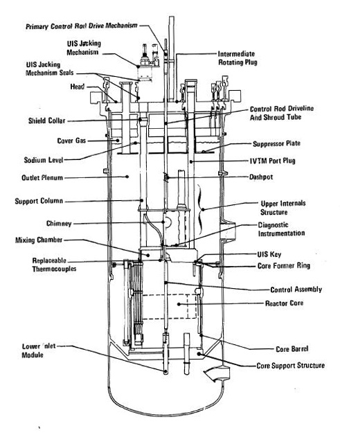
Figure 4 CRBRP reactor vessel
The reactor vessel is surrounded by a guard vessel as shown in Figure 5. The figure has been rotated counterclockwise 90 degrees so the captions are readable. The guard vessel extends above the outlet nozzles and guards the inlet and outlet piping up until all those six pipes turn to the horizontal direction. The primary system piping (discussed in Section 7) runs at a constant elevation between the primary system components. Guard vessels also surround the primary pumps and the Intermediate Heat Exchangers (IHXs). The elevation of the tops of all the guard vessels is uniform.
Guard vessels are a characteristic feature of sodium cooled plants. The idea behind them is that if there is a primary system leak at one of the components, the leaking sodium will fill the guard vessel until the sodium level in the guard vessel is the same as the leaking component. A leak in the elevated piping (See Section 7 for a discussion of this “elevated piping”) would theoretically flow to the floor of the vault in which it is located, but much of the leak would freeze at the leak site. particularly if the leak is small. Basically, the “elevated piping” is the piping that connects the primary system components (RV. primary system pumps, and IHXs). It is above the level of the guard vessels and is unguarded. Such a leak would empty the sodium in the branch of the piping between adjacent components, disabling that loop, but only that loop. In a sense, guard vessels provide much the same protection as the containment in a PWR. Both are intended to protect against major primary system piping failures. This guard vessel concept can only apply to systems where the reactor coolant pressure is close to atmospheric, thus requiring a coolant with a high boiling point. One of the design criteria is to ensure there is sufficient sodium in the reactor vessel above the top of the outlet nozzles to ensure the nozzles remain covered in the event of a reactor vessel leak. The same criterion would not necessarily apply to the IHXs and primary pumps but they must be guarded anyway to prevent siphoning the RV. The guard vessel concept also explains why there were three loops in CRBRP. Each of the primary loops played a role in decay heat removal. If one of the loops were breached, two more loops would be required to meet the single failure criterion, a ground-rule for safe shutdown design since the early days of nuclear power.
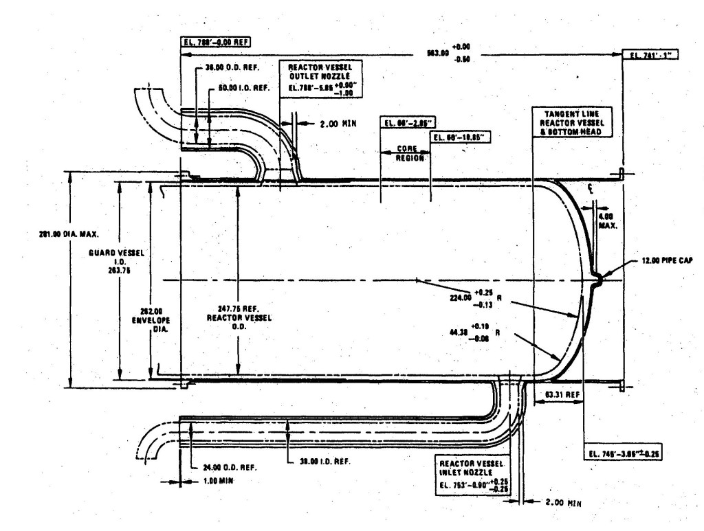
Figure 5 CRBRP Reactor Guard Vessel
The space between the tops of the fuel assemblies and the suppressor plate was provided for horizontal translation of core assemblies by the In-Vessel Transfer Machine (IVTM) during refueling operations, described later. This was at least 14 feet of reactor vessel length on CRBRP and for the fuel design approach proposed in this monograph, it would be in the 11-11 ½ ft. range. The difference between the CRBRP fuel assemblies and the “design approach” assemblies, 2 ½ – 3 ft. (see Appendix 2B for a discussion of this feature) represents the first cost reduction measure (CRM) for the “design approach”. This difference is achieved through elimination of the fuel assembly gas plenum, shortening of the fuel assembly inlet plenum, and shortening of the upper axial blanket while lengthening the fueled region by one foot. In fact, given that refueling is partially accomplished using an IVTM, this fuel assembly length difference is realized twice, first in the core barrel length and second in the outlet plenum length.
The lower inlet modules were primarily provided to permit shuffling of the blanket assemblies during refueling, since they were orificed for all radial blanket positions. The idea was that when a radial blanket is shuffled to an outer row, it requires less flow. This could be accommodated by the orifices in the lower inlet modules.
Elimination of the lower inlet modules is the second action that is herein being advanced as a cost reduction measure. Since the design approach being proposed does not require blanket shuffling, there is no need for these inlet modules. The core assemblies can be loaded directly into the core plate, which is the bottom forging in the core support structure, which was the approach used on the FFTF, the predecessor plant to CRBRP. In CRBRP, there were 61 of these lower inlet modules and their associated liners. Although they were never procured by the project, the expense of these devices would have certainly registered in the millions aside from their impact on the reactor vessel. A further incentive for eliminating the inlet modules is the elimination of the pressure drop that occurs across them and the coolant flow that is lost by leakage. Inlet module elimination subtracts about 3 feet from the length of the reactor vessel.
The lower inlet modules also added three feet to the length of the core barrel. A figure of one of these lower inlet modules inserted into its module liner is provided below. Dimensions are in inches.
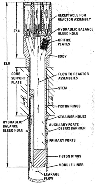
Figure 6 CRBRP lower inlet module
Since it was not possible to support the entire set of removable shield assemblies with these lower inlet modules, it became necessary to design so-called bypass flow modules to accommodate the outer peripheral assemblies. Six large bypass flow modules were intended to be installed in the reactor outside these lower inlet modules. All this hardware came at a high cost both in design and fabrication, added an additional component that could fail, increased the pressure drop across the reactor vessel by up to 8.66 psi, increased hydraulic leakage scavenging coolant away from the core, and turned out to be unnecessary. All of the core assemblies could have been inserted into the core support plate at the bottom of the core support structure as was done on the FFTF. Passages could have been provided in the core support plate for the bleed flow necessary to make hydraulic hold down work. (Hydraulic hold-down is described in Appendix 2D under “Thermal-Hydraulics Design” and a figure is provided.) In fact, passages were provided in the core plate anyway to enable hydraulic hold down for the lower inlet modules.
The orifice plates provided in the lower inlet modules to permit radial blanket assembly shuffling proved to be unnecessary since the nuclear designers wound up having no intention of shuffling blanket assemblies. This happened on CRBRP because the reactor vessel and internals design was ahead of the core design24. The internals designers knew the lower inlet module concept would require lengthening the reactor vessel and needed to commit on a conceptual approach since a RFP was about to be released for reactor vessel fabrication.25 The internals designers anticipated a nuclear design requirement (shuffling of blanket assemblies) that didn’t materialize. Although well intentioned, the whole lower inlet module exercise turned out to be a waste of time and money. It is an object lesson of the need to have high confidence in the nuclear design before making irreversible commitments on other parts of the plant design.
The reduction of the pressure drop across the reactor which is also described in Appendix 2D is a significant cost reduction measure as it reduces the design requirements on the PHTS pump, reduces pumping power making more power available to the grid and eliminates the need for hydraulic hold-down of the fuel assemblies. These steps constitute items three and four of the cost reduction measures. Since the fuel assemblies are proposed to be vented to the coolant, gas tagging is not possible, therefore creating a fifth cost reduction measure, the elimination of gas tagging. It should be noted that gas tagging was not a requirement on CRBRP to satisfy any regulatory requirement. There is more on this subject in section 12.
The head shielding on CRBRP was provided to permit head area access shortly after shutdown when Na24 activity in the coolant is high. For the refueling approach proposed here, Na24 activity is allowed to decay before head area access is needed. The head shield represents another 3-4 feet of RV length. If one adds the reductions that can be obtained from elimination of the transfer space, elimination of the fuel & blanket assembly gas plenum, elimination of the lower inlet modules, and elimination of the head shielding, there is a reduction potential of 25 feet in reactor vessel height. Head shield elimination constitutes CRM 6. Steps that can be taken to eliminate the transfer space are discussed later in this section.
The SRE and Hallam Reactor Vessels
The ellipsoidal lower head on CRBRP is suspect. It possibly provides greater strength, better flow distribution, and a lower pressure drop than a flat bottomed head but it may also be no more than an unnecessary carryover from LWRs, where the high pressure coolant dictates configurations like this. In fact, the pressure drop across the inlet plenum was predicted to be a rather high 5.8 psi, which is either a conservativism or possibly a consequence of the lower head design. The figure below shows an early concept for the Hallam reactor vessel.26 The designer of Hallam (then North American Aviation, later Rockwell International) had no previous experience designing LWRs. Hallam followed the Sodiun Reactor Experiment (SRE), also designed and operated by North American Aviation.
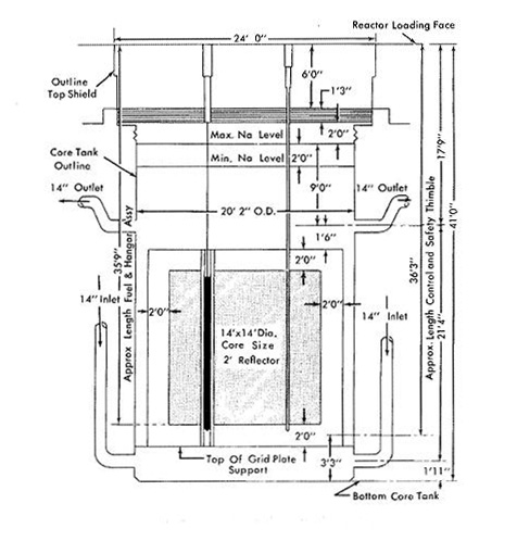
Figure 7 Hallam reactor vessel
The Hallam core had a thermal spectrum that was moderated with graphite so the core dimensions are not relevant to this discussion. However, the flat bottom is evident. In addition to reducing vessel height, removing the ellipsoidal lower head could simplify bottom mounting of the vessel. Bottom mounting the RV removes much of the tensile load off the RV wall which would permit thinning the vessel wall. A second important difference is the absence of a core barrel. The core assemblies, moderator, and fuel appear to extend to the thermal shield. Presumably, there was some sort of fixed shield between the core assemblies and the thermal shield to accommodate differences in the geometry between the core assemblies and the cylindrical thermal liner. A third important difference is the absence of an Upper Internals Structure (UIS). The UIS served three functions on CRBRP: 1) backup holddown of core assemblies, 2) a place to locate core exit thermocouples, and 3) a place to mix sodium exiting fuel, blanket, control, and shield assemblies having widely different temperatures. It is noted that there is no need for a structure to promote mixing in the design approach and the need for a structure to promote mixing is not obvious. A fourth difference is a significant shortening of the distance from the top of the core assemblies to the bottom of the RV head. The reason for this will be explained in the subsequent discussion. A second, more detailed rendering of the Hallam RV is presented below. 27
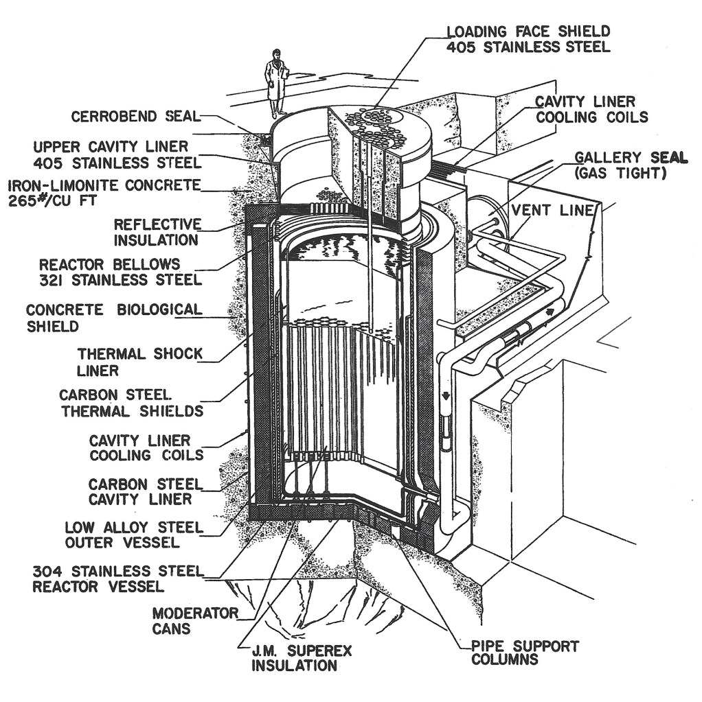
Figure 7a Hallam Reactor Vessel
From the above drawing, there appears to be some sort of standoff between the bottom of the RV and the guard vessel that is aligned with the support posts for the grid plate. This contrasts with the SRE configuration where the RV rests on the guard vessel (see figure 8). The guard vessel appears to be riding on some sort of bearing arrangement mounted on the insulation. The thermal shield (identified as the “thermal shock liner”) extends down to the grid plate and there is a bellows at the top of the RV to accommodate thermal expansion between the fixed RV bottom and the fixed closure head. Since there is essentially no tension in the vessel wall at the location of this bellows, it can be as thin as necessary to support operability of the bellows. Tetralin, the same cooling fluid that was used for the seals of the PHTS pump on SRE, was supplied to channels in the surface of the concrete facing the RV.
One of the questions which emerges from close inspection of figure 7a is how thermal expansion of the bottom of the guard vessel is accommodated. The wall of the guard vessel is hard up against the surrounding insulation. If the horizontal constraint resulted in the bottom of the guard vessel bowing upward, the result would likely be serious. Another question would pertain to the support structure for the guard vessel. There are 79 support columns each 18 in. in diameter and 25 in. high fitted with a cap on top. 28 Again, there is the question of whether the vessel moves over the caps attendant with thermal expansion. The outer vessel is low alloy ferritic steel while the RV is 304 SS, so the two will expand at differing rates (austenitic having the higher thermal expansion coefficient than ferritic) andthe temperature of the RV is likely to be higher than the guard vessel. How the relative motion between the two is accommodated is not clear.
There is a bellows at the top of the RV wall. This is a consequence of a fixed bottom and a fixed head. The head is supported by the operating floor deck which is a massive shield. It is necessarily heavy to allow access to the head area while Na24 levels are high. If the requirement for access to the head area during operations is removed, the head thickness can be reduced to about 2 ft. and can be supported by the RV. The bellows is not necessary if the head is supported by the RV and is permitted vertical movement associated with temperature changes. A bellow connecting the RV and the vault wall would probably be required to adequatelyu seal the inerted reactor vault.
Of all of the features of the Hallam RV which differentiate it from the CRBRP, the most important is likely the bottom mounting. Bottom mounting takes the heavy load off the RV wall and enables supporting the core plate (or core grid as it was called on Hallam) off the bottom. Bottom support of the core plate would permit reduction of its thickness, and the support posts would possibly promote better mixing in the inlet plenum. Elimination of the core barrel would permit reduction of the RV diameter but it may pose a problem for core restraint (not required in a sodium thermal reactor) which can impose heavy loads on the relatively thick core barrel. Possibly, the thermal liner could be thickened so as to serve a dual purpose, but such an approach is left for further study. The UIS continued to provide a convenient means for measuring core assembly outlet temperatures. The core barrel and UIS will therefore be retained in the “design approach”, but the flat bottom will be adopted.
While the elimination of the core barrel and UIS are both worthy ideas and should be evaluated further as part of any preliminary design activity, the elimination of the lower ellipsoidal head and bottom mounting of the vessel will be carried forward in the :design approach” and constitute CRMs 7&8.
One design question regarding this approach is how one accommodates thermal expansion at the point where the bottom of the vessel contacts the support structure. For the case of the reactor plant SRE, which was predecessor and supported similarly to Hallam, there was no space between the reactor vessel bottom and the guard vessel – i.e. the reactor vessel was in contact with the guard vessel while outside the vessel wall there was an annular space filled with helium, surrounded by a “thermal shield” which was in contact with the guard vessel. The guard vessel was supported by a bearing plate, which consisted of circular rings of insulating material. A diagram of this arrangement is shown below, 29
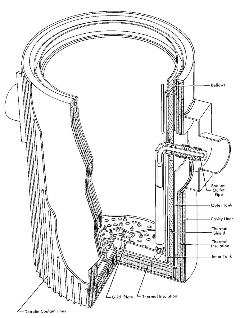
Figure 8 SRE Reactor Vessel Installation
While it is encouraging that the most obvious problem of bottom mounting was addressed on this early design, there remain a host of questions, such as how the bearing rings are configured so as to allow for differential expansion between the vessel bottom and the underlying concrete. Serious consideration of bottom mounting the reactor vessel must begin with a careful review of how SRE and Hallam resolved these problems followed by determination of whether the approaches used will scale up to the sizes envisioned in this paper. Some form of demonstration involving a mockup would likely be required to establish confidence in its suitability for long term application. Despite these uncertainties, the configuration proposed will adopt the bottom mounted approach as a cost reduction measure for reasons that will become clearer as the discussion in this section advances. Later in this section, a trade-off between the top mounted and bottom mounted approaches will be made. If the bottom mounted concept proves to be unworkable, fallback to the conventional flange mounted concept would be available at an economic penalty. As an aside, it is worthy to note that the BN-600 pool reactor is bottom mounted off a skirt. The bottom of the BN-600 pool is ellipsoidal and not flat.
CRBRP Refueling Approach
At this point, it becomes necessary to consider refueling, which had a significant impact on the CRBRP reactor vessel. Compared with the refueling procedure and equipment required for a LWR, the typical LMFBR refueling system is remarkably complex. This complexity is the combined result of using sodium as a coolant and requiring rapid refueling – on the order of two weeks – and starting the refueling process shortly after shutdown while Na24 activity remains high. Although the refueling system for Superphénix is different from CRBRP, it is no less complex so CRBRP provides a decent baseline for evaluation, which will be used here. A composite figure of the CRBRP refueling system is shown below. The Superphénix scheme will be discussed later.
There are four major components that constitute the refueling system: the three rotating plugs that form most of the reactor head, the In-Vessel Transfer Machine (IVTM), the Ex-Vessel Transfer Machine (EVTM), and the Ex-Vessel Storage Tank (EVST). These four components are shown in Figure 9, below. The figure also shows an Auxiliary Handling Machine (AHM), which was used primarily for installing the in-vessel section of the IVTM and a Fuel Handling Cell (FHC) whose main purpose was to receive new assemblies and prepare spent assemblies for shipment.

Figure 9 CRBRP Refueling System
The reactor closure head, shown in the figure below, consisted of three rotating plugs mounted in the vessel flange. The rotating plugs were provided to give access for the IVTM to the in vessel assemblies (fuel, blanket, control, and shield) through a port in the small rotating plug and allow the IVTM to transport such assemblies inside the reactor vessel into a Core Component Pot (CCP) which was placed in a transfer position located outside the core barrel. The CCP was provided to keep fuel, blanket, and control assemblies covered with sodium for cooling purposes while they are being withdrawn from the reactor and into the EVTM. After a core assembly had been loaded into a CCP, the large rotating plug could be adjusted to place the EVTM directly over the transfer position, giving the EVTM access to the CCP containing the selected core assembly. This arrangement is rather typical with one important exception – most sodium cooled reactors have just two rotating plugs, which give complete access to all core locations. The reason CRBRP had three harkens back to an early decision to use the FFTF hydro head on the project, fixing the reactor vessel diameter to FFTF’s 20 ft. The idea was that the FFTF hydro head could ultimately be used as the material for fabrication of the CRBRP head, an idea that was never proven, since the project was terminated before the head was fabricated. Had the vessel diameter been a little larger, two plugs would have sufficed, but at 20 ft., it turned out to be necessary to have a third plug to give access to all the core assemblies and the transfer position. Eliminating the small rotating plug by giving freedom to the vessel diameter is an obvious and easy cost reduction measure and is identified here as CRM 9.

Figure 10 CRBRP Closure Head
Even without the small rotating plug, it is evident from the figure that this head system is complicated and badly congested. To make matters worse, the control rod drive mechanisms are not shown, nor are the UIS jacking mechanisms, nor are any of the gas purge lines, nor are the plug drive motors, nor are required electric power cables. Conjestion at the heart of the plant slows and complicates construction, operations, and maintenance.
Consider the removal of a spent fuel assembly. First the head gas seals are deflated, the head freeze seals are melted, the control rod drivelines are disconnected and raised, and the upper internals structure is raised about nine inches by a jacking mechanism on the reactor head to permit rotation of the plugs. Using the polar crane, a floor valve and adapter is installed over the IVTM port. A typical floor valve is shown in the figure below. The Auxiliary Handling Machine (AHM) couples with the IVTM port adapter (not shown) and the space between the AHM valve and the IVTM port valve is evacuated and purged with argon, many times if necessary. The valves are then opened, the AHM then removes the IVTM port plug from the SRP through the floor valves, the valves are then closed, and the AHM stores the plug and transports the in-vessel section of the IVTM to its location over the SRP port. The same valve purging sequence is followed, the in-vessel section installed, the AHM removed and stowed, and the drive section of the IVTM is installed using the in-containment crane. Once the IVTM is fully installed, the IVTM then has access to the in-core assemblies. Next, a core assembly is grappled by the IVTM, the IVTM raises the assembly to clear the core, and the rotating plugs are activated to transfer the assembly from its existing lattice position to a transfer position located between the core barrel and the reactor vessel. This step is taken so the IVTM can lower the core assembly into a core component pot (CCP) which had previously been installed in the transfer position. During these operations, the equipment hatch between the RCB and the RSB is removed.
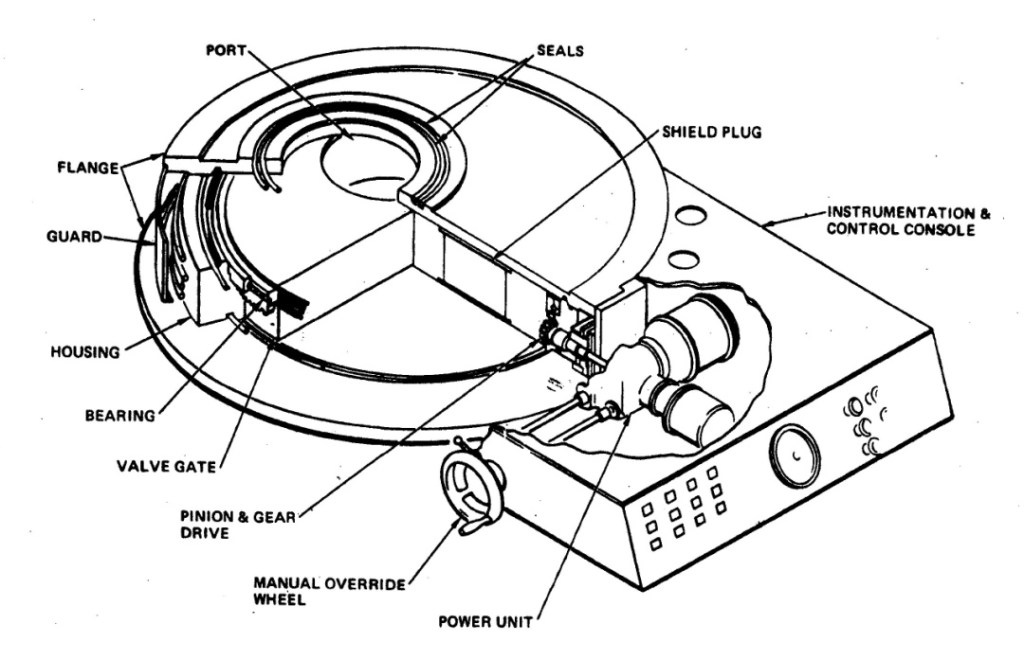
Figure 11 Floor Valve
It should be noted that in vessel transfer machines come in various configurations. The FFTF used a machine with an offset arm to improve its reach to the transfer location. An alternative to the offset arm is the pantograph, which is basically a collapsible offset arm. An offset arm or pantograph could be configured to replace one of the rotating plugs. On the CRBRP project, there was an objection to both the offset arm and the pantograph. Since the offset arm is obliged to remain in the reactor where it is exposed to the full range of reactor transients accompanying operation, there was a concern that it may become stuck requiring removal. To remove the offset arm would require removal of the rotating plug through which it penetrates – a major operation involving a lengthy shutdown. The project participants saw this as a very undesirable prospect and objected to the offset arm. A pantograph could be removed from the reactor after refueling and not be exposed to the reactor operating environment. However, the pantograph was considered undesirable out of concern that it could become stuck in the extended position similarly requiring an extended shutdown for recovery. So, the CRBRP project adopted a straight through in-vessel transfer machine (IVTM).
The spent fuel is transferred to an ex-vessel storage tank (EVST) located outside containment in the Reactor Service Building. To get outside containment, the EVTM must pass through the equipment hatch in the containment building wall. The hatch is about 75 ft. in diameter.26 After the hatch is removed, it is necessary to install bridge rails for the EVTM. Similar to the reactor, a floor valve is attached to one of many ports in the EVST with an adapter that mates to the EVTM. Assemblies in the EVST, both new and spent, are loaded into receptacles in a carousel which rotates inside the tank. The receptacles are arranged in concentric circles which are accessed by the ports at the top of the EVST, one for each concentric circle. Once the EVTM has finished with an entire circle, the floor valve on the EVST is moved to the next circle of interest. The EVST is filled with sodium at some nominal temperature (around 400°F.) and is actively cooled. On CRBRP, there were two levels for storage in the EVST and a total capacity of over 800 assemblies could be accommodated. For CRBRP, this would have been enough storage for approximately three full core loads.
Another refueling facility in the Reactor Service Building is the Fuel Handling Cell (FHC). On CRBRP, this facility did not proceed beyond conceptual design. The purpose of the FHC was to provide for loading spent fuel to a shipping cask and accept new fuel prior to its loading into the EVST. The CRBRP project had never provided for sodium removal of spent fuel or shipment of spent fuel in water cooled casks. There was no shipping cask design that was developed to accommodate the plant’s spent fuel. At the time of the project’s termination, there was no provision for removal of the hatch between the containment and reactor service buildings. While none of these were intractable problems, it would seem reasonable to expect that any shipment of spent fuel that travels over public roads would be required to occur in water cooled casks so removal of the sodium from the spent fuel would need to be provided for.
Returning to the reactor head, figure 12 shows some of the details of the head riser. With the small plug eliminated, there would remain a large rotating plug supported by the reactor vessel flange and an inner rotating plug supported by the large rotating plug. The IVTM nozzle would be located adjacent to the inner plug riser. The inner plug houses the control rod ports and the support columns for the Upper Internals Structure (UIS). Supports for the suppressor plate are located on both the large and inner plugs. The drive motor for the inner plug is mounted on the large plug. At the top of the risers are located inflatable seals, which are normally inflated but are deflated when the plugs are being rotated. Sealing during plug rotation is provided by sodium seals located at the bottom of the risers. During plug rotation, the seals are purged with argon to prevent sodium oxidation. The weight of the inner plug is transmitted to the large plug by ball bearings at the top of the risers. The plugs are driven by drive motors whose pinions engage teeth on bull gears on the outsides of the tops of the risers.
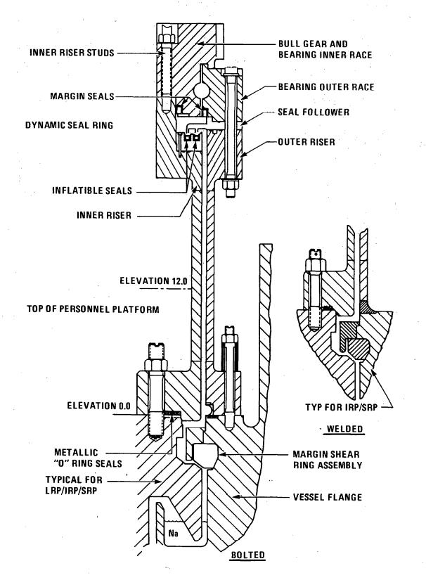
Figure 12 Head Riser system
The EVTM and IVTM are shown below as Figures 13 and 15. It is the task of the EVTM to move fresh and spent fuel back and forth between storage and the reactor. The EVTM is a vertical tube including a cold wall, which serves as a heat sink, into which the fuel assemblies are loaded and is supported by a gantry trolley. The trolley rides on rails with a span of 13 ft. The trolley is supported by a gantry that rides on rails with a 30 ft span. At the bottom of the EVTM tube is a valve, normally referred to as a floor valve, which isolates the environment inside the EVTM from the outside air. At the top of both the reactor and the EVST is mounted yet another floor valve with an adapter that mates to the EVTM. The EVTM begins the refueling operation at the EVST, by obtaining a new fuel assembly contained within a Core Component Pot (CCP). The EVTM then moves to the reactor where the Large Rotating Plug (LRP) has been rotated to be aligned with an unoccupied transfer position. When the EVTM has mated with the adapters and floor valve atop the LRP, the air space between the two floor valves is first evacuated then purged with argon. Once the oxygen has been satisfactorily removed possibly requiring repeated evacuations and purges, the two floor valves are opened, and a hoist located within the EVTM and carrying the new fuel assembly in its CCP is lowered into the unoccupied transfer position. The grapple is then partially retracted.
At this point, it becomes necessary to describe another interesting (and complicating) feature of the CRBRP refueling system. A Rotating Guide Tube (RGT) was installed in the reactor directly above the transfer positions. The Reactor Fuel Transfer Port (RFTP) adapters, when installed, mate with the RGT and include the RGT drive system. The RGT had an offset such that rotation of the RGT positioned the offset at either of two adjacent transfer positions. This RGT is shown in the figure immediately following the EVTM. This feature permits the EVTM and the LRP to remain stationary while a new fuel assembly is being loaded and a spent assembly is being withdrawn. This RGT drive system is one more item to congest the head area.
Following the loading of the new assembly, the RGT is rotated so that the lower offset tube is positioned over the spent assembly. The grapple is lowered and engaged to the CCP holding the spent assembly, the CCP and spent assembly are lifted into the EVTM, the floor valves are closed, the EVTM disconnects from the LRP and proceeds back to the EVST. The engaging and disengaging process is accomplished with machinery installed on the EVTM. Decay heat from the spent fuel assembly is radiated to a “cold wall” which is actively cooled by forced convection of air on its outside surface. The EVTM is self propelled by electric motors as it lumbers back and forth from the reactor to storage. Its total weight including gantry, trolley and the EVTM itself was 270 tons. It was designed to be 35 ft. high. All this mass was provided to transport an assembly that was 14 ft. long and weighed 450 lb. Electric power is provided to the machine by cables that wind and unwind as the machine moves back and forth.
The SRE/Hallam Refueling Approach
There are two major simplifications that can be made to this system drawing on previous liquid metal designs. One would eliminate the intermediate rotating plug leaving only one large rotating plug and the second, more dramatic simplification would eliminate both rotating plugs and adopt open vessel refueling. Both schemes would eliminate the IVTM, and with it the need for the transfer volume in the reactor vessel with attendant reactor vessel shortening. Both would also eliminate the need for a transfer position outside the core barrel and would eliminate the core component pots. These three items (shortened RV, no CCPs, and no IVTM) constitute CRMs 11, 12, and 13.
At this point, it would be propitious to bring up an important feature described in Appendix 2C under core design. An objective in the core design was to achieve ten years between refuelings. Since the expected average fuel burnup to achieve ten year refueling intervals is about 15% with peak burnup in the neighborhood of 30%, this objective was the driver for proposing vented fuel leading to first cost reduction item of foreshortened fuel assemblies. This ten year refueling interval shall be herewith identified as CRM #10. It makes long refueling outages feasible since they occur so seldom, relaxing refueling requirements that had been imposed on CRBRP in the interest of minimizing refueling shutdown time.

Figure 13 CRBRP Ex Vessel Transfer Machine

Figure 14 Rotating Guide Tube
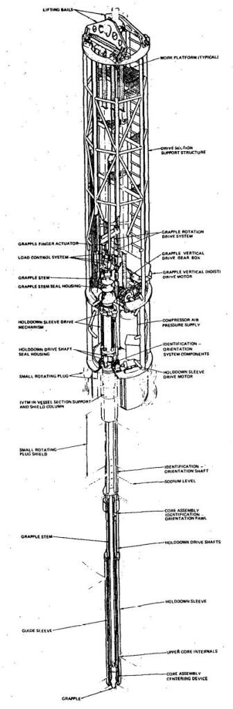
Figure 15 CRBRP In-Vessel Transfer Machine
The first idea, a single rotating plug, draws on the refueling design of the Sodium Reactor Experiment (SRE), a graphite moderated sodium cooled reactor. The SRE had a single rotating plug centered over the core with ports located in the head in such a fashion that by selection of a port and rotation of the head it would be possible to position a port over any individual core assembly. The SRE had a fuel assembly and core design that was very different from the LMFBR design, but features of this approach could be adapted to the design approach being considered herein. The significance of the SRE system (as well as Hallam, for that matter) for this discussion is there was no in-vessel transfer machine so no need to provide the volume above the core to make such transfers. Core assemblies were removed directly from the core into a fuel handling cask where they were transferred to a cleaning cell and a storage cell. This approach has some of the key advantages of open vessel refueling in that it permits a shortened vessel and eliminates the transfer positions. If open vessel refueling (discussed later) proves to be too much to swallow, this scheme would be a good alternative. A photograph of the SRE reactor head and refueling machine appears below.27
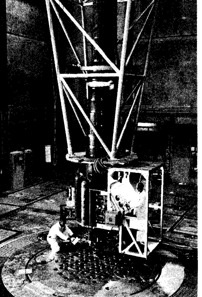
Figure 16 SRE fuel handling system
A large scale fast reactor has many more (and smaller) assemblies than SRE, but likely the same approach could be used with a centered rotating plug similar to the SRE plug described above. Because of the 12-fold symmetry of a hexagonally patterned core, it would not be necessary to have a port for each core assembly, assuming the rotating plug is centered over the core. For example, the core described in Appendix 2C has 847 fuel, blanket, and control assemblies would require at most 74 ports, many of which could be eliminated depending on the tolerance of the transfer machine for misalignment. In this regard, there is a tradeoff between the size of the ports and the number required. The larger the ports, the fewer will be required. There would be some details needing to be worked out, e.g. the access ports to the first and second rows are adjacent, so special ports would be needed there; the CRDM penetrations would need to be compatible (i.e. not excessively large) and the drivelines, which would move with the rotating plug, retractable so as to clear the core assemblies. It may prove necessary to modify the core design somewhat so that the control assemblies do not appear in symmetric positions. There is a more extensive treatment of this subject in Appendix 2G.
The fuel handling machine would be obliged to furnish the function served by the core component pots by having some sort of shroud, closable at the bottom that would be lowered into the sodium pool through one of the head ports. The shroud would be evacuated, presumably of argon or helium, drawing sodium up into the shroud, then a grapple would be lowered through the shroud, engaging the core assembly, the core assembly would be withdrawn into the sodium filled shroud, the lower valve would be closed, then the shroud containing the sodium covered core assembly would be fully withdrawn into the EVTM. Assemblies that are 7.19 in. across the flats will be 8.30 in. from corner to corner. Allowing 0.125 in. thickness for the shroud, the port diameter would be about 9 in. for a cross sectional area of 63.5 in.2, which compares with the core assembly cross sectional area of 44.77 in.2. There will be plenty of room on the head for these ports. The biggest complication with such a scheme is the UIS, which would interfere with access to the core assemblies. It would be necessary to design the UIS (as well as the suppressor plate) so that there would be access to the core assemblies below each port in the head. This would not have been a feasible approach on CRBRP since the UIS was obliged to provide backup hold-down for the core assemblies. There is no need for hold-down in the design approach herein proposed. The suppressor plate would also need to be supported from the rotating plug and have holes aligned with all the ports. Alternatively, the suppressor plate could consist of two parts, one connected to the fixed portion of the head and the other to the rotating plug.
Since the rotating plug would probably be about 22 ft. or more in diameter to allow access to shield assemblies, space could probably be found for at least 50 of these ports. For the core design shown in figure 45, a minimum of 16 ports would be required. A number between 30 and 50 would probably prove adequate. Assuming a pattern could be found that would provide complete coverage of all the core assemblies, there would be no further need for the intermediate rotating plug, eliminating the IVTM and allowing the reactor vessel to be shortened by another 12 ft. Elimination of the intermediate rotating plug constitutes CRM 14. A conceptual port pattern has been devised and is described in more detail in Appendix 2G. The pattern provides 32 ports and requires a tolerance of plus or minus 0.8 in. corresponding to a port diameter of 10.1 in. Seven of the ports access a single assembly (within the 1/12 core sector, therefore accessing 12 assemblies in the whole core) and can accordingly be reduced in diameter, if desired. Other patterns undoubtedly could be devised.
The EVTM complexity is increased somewhat by the provision of the valved shroud and siphoning system. However, if the EVTM is operating fully within a refueling cell (described below), the shielding, which constitutes a great deal of the weight of the CRBRP EVTM, could be significantly reduced or eliminated. The shortened fuel assemblies should reduce the length of the machine an equivalent amount. The machine would have a short travel distance to the EVST and would not pass through an equipment hatch.
It needs to be pointed out that for a removable assembly diameter of 22 ft., (the core diameter is 18 ft. and is surrounded by 2 ft of removable shield assemblies) if two rotating plugs were to be used, the vessel diameter must grow to at least 44 ft. For two rotating plug refueling, the Upper Internals Structure (UIS) needs to be rotated out of the way of the assemblies to be refueled. One might design the UIS so it does not cover the shield assemblies, but the point is that a reactor vessel diameter in the 30 ft. range is not consistent with two rotating plug refueling unless the UIS is eliminated.
The SEFOR Refueling Approach
The ultimate in simplicity that eliminates the need for any rotating plugs was that selected for the Southwest Experimental Fast Oxide Reactor (SEFOR). In SEFOR, an argon inerted, shielded hot cell was located above the reactor provided with lead glass windows and periscopes, mirrors and television camera so that fuel elements could be removed from the reactor and examined. The cell was used for refueling and for transferring fuel from the reactor to an irradiated fuel storage tank located in the cell and from the fuel storage tank to a cask for shipment off-site. All operations within the cell were visible to the operators. An outline figure of the approach used at SEFOR follows:

Figure 17 SEFOR Vessel and Refueling Cell
The following is drawn from a reference on SEFOR operation: “Extensive fuel transfer operations were accomplished, including approximately 2000 fuel transfers. This experience demonstrated the ease which fuel can be visually located and then grappled and transferred by remote mechanisms. Fuel rod transfers in a 15-min. time interval are limited only by the crane speed. Reflections from the silvery sodium pool contribute significantly to the ability to see and identify core locations. This favorable operation has confirmed the design basis for open-pool, hot-cell refueling, and gives increased confidence to LMFBR designs utilizing this form of refueling. Broad experience was also obtained with the refueling cell man-access suits. Many refueling cell maintenance and repairs have been accomplished, and a high degree of competence has been achieved with men working within the suits. More than 60 cell entries have been made and over 80 man-hours of in-cell operations logged.”32
The idea of a hot cell with lead glass viewing windows, cranes, and manipulators, located directly above the reactor is foreign to anyone with commercial nuclear reactor experience and it creates the impression of an experimental facility. Manned entry through an air lock raises questions of ready accessibility and personal safety. Contamination levels in such a facility could be high and decontamination would be tedious and difficult. It is probably for these reasons that the SEFOR refueling approach was never pursued on any follow-on plant. However, for the design approach considered here, the cell need not be inerted except on rare refueling occasions or when new or spent fuel is being shuffled from row to row in the Ex Vessel Storage Tank (EVST). Following fuel handling operations, the cell would be deinerted and decontaminated.
It is important to point out that there is relatively little description of SEFOR in the open literature available on the internet. From the information available, there is no way to tell what the Upper Internals Structure looked like, how it was supported, and how it was dealt with when the head was being removed. Another area of uncertainty is the control rod mechanisms and how they were accommodated during head removal. It appears, from Figure 17, that the control system was operated from below the reactor and consisted of reflectors rather than absorbers. SEFOR was designed by General Electric, so somewhere in the General Electric document control system there must be answers to these types of questions. Since General Electric submitted a bid for the CRBRP design contract, their proposal may have included open vessel refueling, in which case there could exist another rendering of this type of approach at a larger scale than SEFOR.
If the single rotating plug option were selected, the UIS would be supported from the rotating plug, jacked up to a storage position prior to head rotation, and would rotate along with the inner plug, the suppression plate, and the control rod drivelines. Both the single rotating plug and the open vessel options accomplish a significant reduction in the reactor vessel height and lead to simpler refueling systems. Both capitalize on the loop-type design approach in a way unavailable to pool-type designs. Of the two, the open vessel approach is probably the more economic. Of the two, the open vessel approach is more likely to arouse virulent opposition. To avoid this, the single rotating plug is selected for the current design approach. More will be said about the open vessel approach and the two will be carried forward in parallel in the interest of understanding the criteria for selection between the two. Once a reliable cost estimate has been accomplished for the base plant design, and the cost impact of adopting the single rotating plug is known, the entity responsible for proceeding with plant construction will be armed with better information and thereby be in a better position to make a considered decision among these two alternatives.
The EVST arrangement proposed here is applicable to either refueling system arrangement. The tank itself is smaller (no CCPs), the large hatch between the containment and the Reactor Service Building is eliminated, the Reactor Service Building itself is reduced to little more than a Transfer Room (plus whatever space is required to house necessary auxiliaries, which would be considerable), a fuel handling cell, and a shipping room, and is represented here as cost reduction measures 15, 16, and 17. These ideas (without a single rotating plug) are captured in Figure 19.
The EVST should be cooled by natural circulation capable of operation under station blackout conditions. There is little advantage of providing natural circulation cooling to the reactor if spent fuel in the EVST is exposed to failure on the occasion of station blackout. A two tier tank as was designed for the CRBRP should be used to reduce tank diameter. All tank penetrations should be through the head in the interest of simplification. A guard vessel should be provided to eliminate leak issues. In the interest of providing better natural circulation for the EVST, the fuel assemblies that have the highest decay heat load should be loaded into the lower tier of the tank so as to lower the thermal center of the contents. The maximum heat load for the EVST is about 3000 KW, which corresponds to the core decay heat five months after shutdown. Two Na/NaK heat exchangers would be located above the tank with two natural draft air cooled heat exchangers provided to remove heat from the NaK. It would be necessary to provide the EVST with a downcomer to return the cooled sodium to the bottom of the tank. The downcomer could either be a set of pipes or the outer annulus of the tank itself. Since the EXST will house no CCPs, it will be more tightly loaded than the CRBRP EVST and may be required to be provided with a built in neutron poison tom achieve criticality control.
For the open vessel refueling case, the fuel assemblies’ decay heat will be about 10 KW two weeks after shutdown and about 5 KW three months after shutdown. The decay heat from blanket assemblies would be about 55% lower. 5-10 KW is too much power to handle naked fuel assemblies inside the refueling cell without cooling of some form. Since there are no core component pots to load assemblies in to, the in-cell core component handling device must furnish the equivalent. One approach might be to lower a handling shroud (similar to the shroud described above in connection with the EVTM with a closed top) which contains the core component grapple to a foot or so above the assembly being withdrawn, siphon sodium into the length of the shroud, lift the core component into the shroud, valve off the bottom of the shroud, transfer the core component to the ex-vessel storage tank, and reverse the procedure. The shroud may require external fins to provide adequate radiative cooling to the fuel handling cell atmosphere.
EVST Placement and Refueling Design/Operation
The ex-vessel storage tank needs to be accessible from both the Refueling Cell and the Transfer Room. Since this is essentially what was done on the Superphénix design for the EVST, this would be nothing new.33 The Superphénix fuel handling system is shown on Figure 18. Superphénix had rotating plugs for in-vessel transfer and had an A-frame arrangement for transfer from the vessel to the storage tank. In Superphénix, only the outer row of the EVST is accessible from the reactor service building handling room. A manipulator on the containment side moved spent and new assemblies between the outer row and interior rows within the EVST with the help of a rotating carrousel on the EVST. The carrousel drive for the EVST was located within containment. For the approaches proposed here, a refueling cell encloses the top of the RV and the side of the EVST nearest the RV including the carousel drive. During refueling operations, the refueling cell would be inerted. Either a Fuel Transfer Machine (FTM) or, for open vessel refueling, the fuel handling cell crane would access RV core components and each of the rows of the EVST during the refueling operation. The EVST would have been preloaded with new fuel & blanket assemblies as necessary to accomplish refueling. There would be no concurrent operations in the Transfer Room during the refueling operation.

Figure 18 Superphénix Fuel Handling System
For the case shown in Figure 19a, the Fuel Transfer Machine (FTM) would be handled by the refueling cell crane, as was done on SRE and Hallam. There would be room for a FTM that had an overall top to bottom length of up to 16 ft. Since the core assemblies length is 11.5 ft., 16 ft. may prove to be inadequate, requiring that the Refueling Cell roof be raised, a rather modest penalty. The FTM could be mounted on rails, but that would require the RV to be lowered about 8 ft. so the rails would clear the rotating plug riser and the UIS jacking mechanism (see Figure 21a). The FTM will require electric power to operate a cooling circuit, the shroud that is lowered into the RV and the EVST, the shroud door, a drip pan installed below the door, and instrumentation. This electric power would be furnished by the crane and if the FTM is mounted on rails, the rails would be fully inside the inerted refueling cell, and could be electrified. Either case would be a hugh improvement over CRBRP, where a cable run to the EVTM was provided which had to move with the EVTM.
The CRDMs require two points of connection/disconnection. The absorber assemblies must be capable of being disconnected from their drivelines so that they can be replaced when needed. The CRDM driver mechanisms must be capable of being disconnected from their drivelines so that the mechanisms can be removed during refueling operations to permit access to the fuel and blanket assemblies. During refueling, the driver mechanisms would be stored on the refueling cell floor. Should any absorber assemblies require replacement during refueling, the FTM must be provided withthe capability to remove the associated driveline.
The following is a listing of the major steps required to refuel:
- Shutdown reactor.
- Wait two weeks for Na24 to decay.
- Enter Refueling Cell and disconnect control assemblies.
- Jack up Upper Internals Structure (UIS).
- Connect Fuel Transfer Machine (FTM) to selected crane and electric power.
- Inert Refueling Cell.
- Deflate riser mechanical seal and melt sodium seal.
- Test head rotation.
- Remove and store Control Rod Mechanisms and drivelines and plug associated head penetrations.
- Use Plug Handling Machine to remove selected head access port plug and instal valve.
- Same as above for Ex-Vessel Storage Tank (EVST).
- Position head over selected asembly, access assembly with FTM, withdraw assembly from Reactor Vessel (RV) and transfer assembly to EVST.
- Return new assembly to RV.
- Access other core assemblies accessible from selected RV head port (see Appandix 2G, Head Port Layout)and return new assemblies to the position vacated. When all planned core assemblies have been replaced with new assemblies, activate Plug Handling Machine to remove valve and reinsert port plug.
- Select another head port and continue as above. There are 32 separate head ports for which this procedure is to be performed.
- At the completion of the replacement of core assemblies, reverse procedure.
After suitable decay of the spent assemblies in the EVST, shipment of spent fuel could begin. The atmosphere in the Transfer Room would be inerted whenever the EVST port is opened or if handling sodium wetted spent fuel is occurring. The outer row of spent assemblies would be removed at the Transfer Room, cleaned with wet vapor nitrogen to remove sodium, and loaded into inerted spent fuel shipping casks. Five years after removal from the reactor, the fuel assembly decay heat will be down to about 1 KW. At such a low heat load, it probably will be possible to handle the assemblies in the Transfer Room without using the handling shroud. The FTM or the refueling cell crane will transfer spent assemblies from the inner rows to the outer row so they can be accessed in the Transfer Room. The operation will not be fast, but it need not be.
When the EVST has been emptied, new fuel and blanket assemblies can be brought in. This probably would not be scheduled until a year or so before the intended refueling outage to avoid unnecessary carrying costs of the new fuel. Since only the outer row of the EVST can be loaded from the Transfer Room, it will be necessary once again to use either the FTM or the fuel handling cell crane to load the inner rows. Sketches of the closed vessel and the open vessel refueling concept in elevation and plan views are shown below. The plan view is at the level of the floor of the refueling cell. Note that the support floor for the IHXs shown in the diagram will be 10-15 ft. above the refueling cell floor.

Figure 19a: Elevation view of Fuel Transfer Machine refueling concept
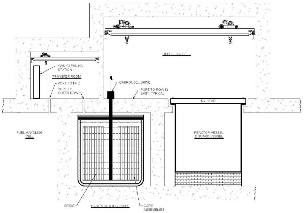
Figure 19b Elevation view of OVR refueling concept
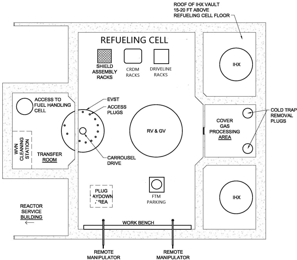
Figure 20a: Plan View of Fuel Transfer Machine refueling concept

Figure 20b Plan view of OVR refueling concept
It is worth considering the advantages of this refueling approach. The items below are made in comparison the CRBRP, but the list would not be much different if the comparison were made with Superphénix: those options that are unique to open vessel refueling are identified with “OVR”.
• The need for rotating plugs on the reactor vessel head is eliminated. This also eliminates the need for the systems required to seal these plugs during plug rotation or plant operation as well as the motors required to accomplish plug rotation. (CRM 18 OVR, but if a FTM is incorporated in the design, a single rotating plug is an improvement over two (or three) rotating plugs)
• The plug risers, which house the seals and bearings for each of the rotating plugs, are eliminated greatly reducing head area congestion. The “design approach” requiring a single riser represents an improvement over two (or three) risers.
• The elimination of rotating plugs removes a source of misalignment of the control rod drive mechanisms improving confidence they will function as intended (see section 10). OVR
• The need for an upper internals structure jacking mechanism is eliminated. (CRM 19) OVR
• The need for shielding under the reactor head is reduced or eliminated, which reduces the length of the reactor vessel correspondingly (about 3-4 feet). (CRM 6)
• The need for space between the core barrel and the reactor vessel is eliminated, enabling the reactor vessel diameter to be reduced by at least 2 ft. (Eliminate transfer positions and required volume between the core barrel and the vessel wall – CRM 20)
• The need for a large inventory of core component pots (the inventory would be set by the number of positions in the EVST plus the transfer positions in the reactor vessel) is eliminated. (CRM 12)
• The need for valves to be mounted on the reactor head and the EVST is eliminated. (CRM 21) OVR
• The need for a machine to handle these valves is eliminated. (CRM 22) OVR
• The need for systems to purge the space between the valves is eliminated. (CRM 23) OVR
• The EVST diameter can be reduced since it will no longer be obliged to house all core assemblies contained within core component pots. Such reduction must be accomplished within criticality control constraints. (CRM 15)
• The EVST size would be set by the number of fuel, blanket, and control assemblies in a single core loading. For the example of the design being considered, that would be 847 assemblies – actually fewer storage positions than the CRBRP EVST was designed for.
• The reactor vessel can be shorter since there is no longer a need for clearance above the core for the horizontal translation of core assemblies. On CRBRP, this was a 14 ft. penalty in reactor vessel height. (CRM 11)
• The IVTM is eliminated. (CRM 13)
• The EVTM is eliminated and both it and the IVTM are replaced with a much simpler fuel handling cell crane. (CRM 24) OVR
• The auxiliary handling machine and plug handling machine are both eliminated. (CRM 23 & 25). A Plug Handling Machine will be required for the single rotating plug option.
• The large hatch between the containment and the reactor service building is eliminated. (CRM 16) The rails through the containment and reactor service building and the bridge rails through the hatch are also eliminated. (CRM 26)
• The entire area under the head is accessible. There is an annular ring of area adjacent to the reactor vessel that is inaccessible with a straight pull IVTM. This may have implications for simplifying the reactor vessel design.
• The requirement for the reactor vessel to be top mounted is eliminated.
Many issues would require resolution of this proposed system for a large commercial plant.
• A provision needs to be made for uncoupling the control rod absorber assemblies. Presumably, the uncoupling operation would be performed two weeks after shutdown to allow for Na24 decay prior to inerting the refueling cell. This could be accomplished manually before the refueling cell is inerted.
• OVR — Following uncoupling of the control absorber assemblies, the mechanisms and their drivelines would require removal. The mechanisms would probably have welded seals on the head, which would require cutting prior to mechanism removal. At the completion of refueling, these seals would require re-welding. During refueling, the uncoupled mechanisms and drivelines would require storing in the refueling cell.
• OVR — The reactor vessel head, possibly fabricated from stainless steel so as to be compatible with the RV, is 2 ft. thick and 30 ft. in diameter and is estimated to weigh about 400 tons. This is probably too much to lift with an overhead crane. Since the only reason for the head being 2 ft. thick is shielding, it could probably be fabricated out of four 6 in. slabs each of which is lifted individually. 100 tons is a more reasonable lift. Lifting fixtures would need to be attached to each piece.
• OVR — Some primary coolant temperature needs to be selected for refueling operations. On CRBRP, refueling was accomplished at a primary temperature of 400°F, but with open head refueling, there will be an incentive to refuel at a lower temperature (probably 250-300°F34) to reduce the heat load to the refueling cell and to reduce the deposition of primary sodium vapor on the refueling cell walls. A lower refueling temperature will require a somewhat larger overflow vessel and greater reactivity control. It would also require highly effective cold traps. Another option may be to allow the refueling cell temperature to rise considerably above ambient.
• OVR — Since plugs will be opened to the EVST, a similar argument may apply to EVST sodium. The opening of a plug does not represent as much heat load as an open reactor vessel, so the EVST temperature can probably be somewhat higher than the reactor vessel temperature.
• OVR — Purity standards for the refueling cell argon (or helium if that is the cover gas being used) need to be established. On SEFOR, there is evidence from the available literature that more oxygen found its way into the coolant during refueling operations than would be acceptable in a commercial plant.
• OVR — Provision must be made for removal of the head and its temporary storage within the refueling cell along with the control rod drive mechanisms. The lifting device used for head removal and its replacement must be single failure proof.
• OVR — It must be demonstrable that there would be no fuel damage if the crane were to fail in transit to the EVST. The means for recovery from such a mishap needs to be devised.
• Fixtures for removal and replacement of the EVST plugs need to be devised.
• OVR — The UIS and the suppression plate must be dealt with in some fashion. Figure 20 shows the UIS as being lifted with the bottom plate of the reactor head as a placeholder. With such a design approach, the lower head plate and UIS would be moved to a UIS parking position, the UIS disconnected, and the lower plate stored with the other head plates. The UIS parking position would be designed with a scale-like arrangement so as to prevent the UIS from being obliged to bear the weight of the lower head plate. Note that the UIS parking position is not shown on Figure 20.
There is another potentially large advantage of open vessel refueling (or the single rotating head scheme that could also embody the refueling cell concept) that deserves mentioning. All LMFBR designers need to consider how they would approach the situation where some large component needs to be removed from inside the reactor and either repaired or replaced. Such an operation very nearly became necessary on Fermi-1 following the fuel melt incident. If something like that were to happen in a plant similar to CRBRP, some kind of a leak-proof tent structure would need to be constructed above the reactor head and the area inerted before one or more of the rotating plugs could be removed. The interior of the tent would need to be outfitted with the handling equipment and fixtures required to accomplish whatever is intended. Very likely, personnel would be obliged to enter this area in personnel protection gear including breathing apparatus. Those who have given any careful thought to how this action would be performed know what a major task this would likely be. It is likely that all the fuel and blanket assemblies would need to be removed and replaced with dummy assemblies to remove that element of risk from the equation. The whole operation would be complicated by the fact that the details would have not been worked out by the original designers and would need to be solved ad hoc and on the spot. If the plant were designed for open vessel refueling, (or single rotating plug with a refueling cell) most of these issues vanish. There already would exist a cell capable of being inerted above the reactor outfitted with handling equipment including remotely operated manipulators, viewing windows, cranes, and fixtures.
The arrangement of the containment, Fuel Handling Cell, the Transfer Room, and the EVST could apply whether there were zero, one or two rotating plugs. The main difference between open vessel refueling and refueling using a Fuel Transfer Machine would be the EVST itself, the head design. It should be pointed out that various hybrid approaches could be contemplated which would be intermediate both in cost and complexity between the design approach recommended here and CRBRP/Superphénix. For example, one could envisage a single rotating plug on the reactor vessel with an offset arm or pantograph IVTM and transfer positions in the reactor vessel containing core component pots. This approach would require only a single port to be opened to the reactor similar to the ports on the EVTM. It would require increasing the diameter of the reactor vessel and an EVTM designed to accommodate core assemblies contained in core component pots. It also would lead to increasing the length of the reactor vessel and would probably require increasing RV diameter to permit handling of components under the head. It would eliminate much of the complexity in the head access area and simplify plant construction.
The Resulting Reactor Vessel Design
The main function of the 10 ft. high UIS on CRBRP was to provide a place where flow mixing occurs from core assemblies with widely different outlet temperatures. The outlet temperature from control and shield assemblies will be considerably lower than the temperature from fuel assemblies and these flows need to be mixed prior to their arrival in the outlet plenum so that any thermal striping is confined to the regions designed to accommodate it. The UIS also performs the functions of backup hold-down of core assemblies (not required in this “design approach”), a location for instrumentation to measure core assembly outlet temperatures, and alignment & protection from cross flow for the control rod drivelines. These functions could very likely be accomplished in less vertical space if there had been an incentive for doing so on the CRBRP project.
On the other hand, CRBRP was a 995 MWth plant design and the concept being advanced here is 3000 MWth, which will require a larger vessel diameter and a sturdier core plate to support a much heavier core. It also may prove necessary to provide some shielding in the core assemblies above the blanket with the gas plenum removed. In the final analysis, design analysis will be required, but there is reasonable basis for optimism that the reactor vessel height can be reduced to somewhere in the vicinity of 30 ft., which would be close to to a 50% reduction from CRBRP for a plant with three times the thermal output. Importantly, none of the reactor vessel dimensions should be finalized until there emerges reasonable confidence in the design of the core, the head closure, and the vessel internals. It also needs to be acknowledged that there may be a price to be paid for a shortened bottom mounted reactor vessel in the way of its seismic response. The inertia of the heavy head may increase the buckling loads on the shortened vessel wall attendant with seismic ground motion. Increased buckling loads may require that the vessel wall be thickened somewhat.
In addition to the above items, a promising candidate for cost reduction would be the UIS itself. For the case of CRBRP, there wasn’t much incentive to reduce the height of the UIS since the space above the core was needed to transfer core assemblies in-vessel with the IVTM. However, because of the potential severity of the thermal striping issue, the provision of a feature in the design to mitigate its effect is necessary. In fact, there was never any guarantee that the CRBRP UIS, fabricated entirely of Inconel, would survive the environment to which it was to be exposed. Experimental efforts focused on the phenomenon usually suggested the problem was real and its effects were possibly underestimated. A desirable course of action is to eliminate the phenomenon altogether by regulating all the core assemblies so that their outlet temperatures are close to equal. While this may be achievable in part, it may prove to be difficult for the control and shield assemblies. To the extent that thermal striping can be reduced, the remaining purposes for the UIS would be to limit cross flow to the control rod drivelines, and have some place to house the core exit thermocouples which would likely not require a structure 10 feet high. There is no need for a requirement to provide backup hold-down since the pressure drop across the assemblies is insufficient to lift them against the force of gravity.
As the vessel height is reduced, at some point the outlet nozzles will begin to become a consideration. The CRBRP hot leg piping was 36 in. in diameter. The Japanese JSFR-1500 outlet piping is designed to be 50 in. in diameter, which is somewhat surprisingly small given that the loop flow in the JSFR-1500 design is nearly five times greater than the loop flow in the CRBRP. This may be a reflection of the shorter piping runs in JSFR-1500 and their corresponding ability to accept a greater head loss per linear foot of piping. In any case, the outlet nozzles of a 1200 MWe plant will certainly be larger than CRBRP, especially since, with the Heat Transport System contemplated (see section on HTS) there are just two of them. It is estimated the hot leg piping would have a diameter of at least 60 in. and the cold leg piping 48 in. Since the outlet nozzles must be above the core barrel, there will come a point where further shortening of the UIS will provide no additional return. There needs to be some margin above the top of the outlet nozzles so as to prevent cover gas from getting entrained into the outlet piping attendant with down transients.
The sketch below (without the CRDMs) is a composite of the ideas expressed above for the open vessel refueling case. A thermal liner is shown, which would be eliminated if analyses establishes that it is feasible to do so. The active core region is 18 ½ ft. in diameter and the control rods and their associated drivelines and mechanisms (not shown) are spread over a roughly circular array about 14 ½ ft. in diameter. The reactor closure head is supported by the vessel, which represents a compressive loading on the 2 in. vessel wall of about 700 psi.

Figure 21 Potential reactor vessel design
As was stated earlier in this section, the single rotating plug option is the one being carried forward for the “design approach”. The head would be different for the single rotating plug case. The rotating plug, supported by the riser, would be one piece and sized so as to give access to all the removable assemblies. Unlike CRBRP, there would be a fixed annulus outside the rotating plug. A port through this annulus could provide access to a DRACS if such a system were desired (see Section 8) but such a provision would probably require a small increase in vessel diameter. Also, it would be necessary to support the UIS and the suppressor plate from the head with a provision for jacking them upward similar to the CRBRP whenever the rotating plug is actuated. Core outlet thermocouple coverage would not be complete because of the need for refueling ports (discussed in Appendix 2G) but assuming the fuel assembly outlet temperatures are regulated at the assembly outlets, a representative thermocouple sampling should be sufficient.
Figure 21a, below, is a rendering of the “design approach” RV, showing outlines of representative primary and secondary CRDMs, the head riser, the UIS jacking mechanism, and a representative refueling port. The single rotating plug is inside the plug riser and the fixed annulus is outside. The loop seal in the head below the risers contains the sodium seal which is normally frozen but is melted during refueling to permit head rotation. Since there are 32 refueling ports, many of which are located in the CRDM area, it would be necessary to remove some or all of the CRDMs prior to refueling. Of course, the CRDMs and core thermocouples must be disconnected electrically prior to head rotation.

Figure 21a “Design Approach” RV
There is another issue connected with the outlet nozzles. On CRBRP it was argued that a breach of the primary system pressure boundary would fill the reactor guard vessel before the outlet nozzles became uncovered. Filling the annular space between the reactor vessel and its guard vessel would lower the sodium level in the reactor by about 2.3 ft. If one adds the annular space between the inlet and outlet piping that is below the sodium level in the reactor, the result is another 1 ½ ft. of sodium level. The outlet nozzles shown in the sketch above are 4 ft. below the normal operating sodium level, so this criterion is satisfied. This argument can be supplemented by pointing out that a primary system pressure boundary failure will leak before it breaks and the primary sodium makeup pumps (to be described later) will be able to keep up with any such leakage. Moreover, any cover gas entrained in the outlet nozzles will wind up in the IHXs which will probably have their own cover gas system connection or a vent since, in this concept, they are the high points of the system. If more space turns out to be needed because of pipe routing or some other reason, the horizontal baffle, which provides lateral support for the core barrel could be lowered along with the outlet nozzles or the vessel length could be increased up to four feet and still be less than half the length of the JSFR-1500 vessel.
The approach shown in the sketch above retains the basic configuration of CRBRP. The core barrel is shown as being 24 ft. in diameter — it could be increased to 26 ft. with little consequence making space available for a larger core or more shield assemblies if proven to be necessary. The UIS internals are shown as having a 7.5 ft. height. With bottom reactor vessel mounting, the load from the core is carried from the core plate through the core support cone to the vessel then downward to the vessel bottom. The core plate is shown as being 3 ft. in thickness, which is a foot thicker than CRBRP in order to accommodate the heavier core. It is likely it is thicker than it needs to be but its required thickness needs to be determined by an analysis that considers all the penetrations. While there are more holes in the core plate than was the case for CRBRP, they are much smaller in diameter since the inlet modules have been removed from the design.
The tensile load on the vessel wall has been eliminated; replaced with a compressive load to carry the weight of the head. It is estimated that the vessel and its contents weigh somewhere in the vicinity of 5,000,000 lb. It the entire load were carried by the vessel wall (it isn’t since the ~1,000,000 lb. weight of the sodium will mainly be borne by the vessel bottom) and the vessel were 2 in. thick, the total compressive load on the vessel wall, including the contribution from the head, would be less than 3200 psi at the bottom of the vessel. Since most of the weight is due to the core itself, one could design the vessel wall to be thinner above the attachment of the core support cone to the vessel wall, if desired.
It is possible that some kind of skirt arrangement will carry some of the load from the vessel wall down through the guard vessel or more likely, the vessel may rest on the guard vessel as was done on SRE or on some kind of Hallam-like standoffs. A thermal liner is shown above the horizontal baffle. It is presumed that some bypass flow will be directed into the annulus between the core barrel and the vessel wall, then outside the thermal liner. The core assemblies are shown with a 10 ft. extension above the core plate with the 1 1/2 ft. inlet hardware inserted into the core plate.
Since the bottom mounted vessel design approach proposed represents a sharp departure from more recent precedent in LMFBR reactor vessel design, below is a summary of the most important advantages associated with each of the two approaches:
- Top mounted vessel
- Vessel head is maintained at a fixed elevation
- Inspectability of vessel welds is simplified
- Proven approach – little R&D required
- No issues with heat conduction to structural concrete other than at mounting flange
- Bottom mounted vessel
- Vessel wall in compression rather than tension – the greatest part of the load is limited to the bottom of the vessel below the core support cone
- Lower seismic excitation since vessel support occurs at a lower building elevation
- The static load on the vessel wall is lowest in the outlet plenum region where the temperature is highest possibly permitting elimination of the thermal liner and associated bypass flow
- Creates (stimulates) option for flat bottom of RV reducing vessel length.
- Creates option for supporting core plate off the bottom of the vessel, reducing core plate thickness.
It may turn out to be feasible to combine the reactor vessel and the core barrel. The volume between the reactor vessel and core barrel was used for transfer positions and in-vessel storage in previous designs, and such functions have been eliminated in this approach. Moreover, the under-the-head refueling approach led to an annular region adjacent to the reactor vessel that was inaccessible to the straight-pull IVTM used on the CRBRP design and therefore useless. Alternatively, the thermal shield could be thickened and serve as a core barrel as was suggested earlier in this section. Both of these approaches would result in a reduced diameter of the RV and probably eliminate the fixed portion of the reactor head. A consequence of doing so would be to eliminate the possibility of adopting the Direct Reactor Auxiliary Cooling System (DRACS) as an option for decay heat removal. It will be shown in Section 8 that the preferred decay heat removal system does not involve DRACS except as an alternative or fallback. However, the DRACS is sufficiently attractive as a fallback option to suggest not taking any steps in the vessel design that would eliminate it from further consideration.
In closing this section, it would be well to do some summing up. The principal incentive for all that has been proposed has been to shorten the RV. In addition to economy both in vessel fabrication cost and the expensive real estate needed to house it, a reduced length reactor vessel comes with additional benefits. The support columns for the UIS are reduced in length. A shorter vessel will have lower seismic response which is further reduced by bottom mounting. The control rod drivelines are shorter and less likely to experience misalignment. There will be a lower pressure drop across the reactor vessel. The instrument lines to the core thermocouples will be shorter. The thermal shield, if it becomes necessary, will be much shorter. It will probably be easier to engage fuel assemblies either with the EVTM for the single rotating plug concept or the refueling cell crane for the open vessel refueling case. The result is a reactor vessel that better performs its function and is more concentrated and focused on containing and getting the heat out of the reactor core.
endnotes
24 There did exist a core design at the time, but the nuclear design did not meet project requirements — a fact that may not have been known to the internals designers. It turned out to be necessary to make major changes to the core design to remedy its inadequacies, all of which occurred after the inlet modules had become a fixed feature of the design.
25 On the CRBRP project, the reactor vessel fabrication contract was let long before it was needed primarily to keep the fabricator, Combustion Engineering, in business. The concern was that if the Combustion Engineering fabricator went out of business for lack of work, there would be no other domestic fabricator who could handle the job.
26 Drawing from Starr, Chauncey; Dickenson, Robert W., Sodium Graphite Reactors, Addison Wesley, 1958
27 Beeley. R.J., Mahlmeister, J.E., Operating Experience with the Sodium Reactor Experiment and its Application to the Hallam Nuclear Power Facility, Atomics International, 1961
28 Gronemeyer, F.C., Merryman, J.W., 75,000 Kilowatts of Electricity by Nuclear Power at the Hallam Nuclear Power Facility, ASCE Convention, Reno, Nov 23, 1960
29 Starr, Chauncey; Dickenson, Robert W.; Sodium Graphite Reactors; Addison Wesley, 1958.
30 Preliminary design on this hatch was not completed at the time of project cancellation. It seems likely the hatch could have been made smaller.
31 Starr, Chauncey; Dickenson, Robert W.; Sodium Graphite Reactors; Addison Wesley; 1958
32 Arterburn, J.O.; Billuris, G; Kruger, G.B.; SEFOR Operating Experience; ASME Nuclear Engineering Conference; Mar. 7-10, 1971.
33 It would be similar to the Superphénix design with one important distinction. The tank would be cylindrical without the bulge for the A-frame. A cylindrical tank would be smaller in diameter (no core component pots), shop fabricated, and much less likely to experience the type of failure the befell the Superphénix EVST, which had been field fabricated.
34 At low temperatures, the risk of plugging becomes significant. The solubility of oxygen at 250 degrees F. is about 1 ppm and about 3 ppm at 300 degrees F. Operation in this temperature range may not be feasible.
